P/N 116087 REV. 9/97 E-72 PROTOCOL™ DIGITAL OVEN CONTROLLER INSTRUCTION MANUAL Prepared by: Despatch Industries P.O.
Notice Users of this equipment must comply with operating procedures and training of operation personnel as required by the Occupational Safety and Health Act (OSHA) of 1970, Section 6 and relevant safety standards, as well as other safety rules and regulations of state and local governments. Refer to the relevant safety standards in OSHA and National Fire Protection Association (NFPA), section 86 of 1990.
Despatch Product Warranty Parts, Materials and Labor Despatch warrants all parts and materials to be free from defects in material and workmanship for a period of one (1) year from the date of shipment unless otherwise mutually agreed upon in writing, or 2,000 hours of operation, whichever occurs first. (Note: Laboratory oven electric heaters are warranted for a period of five [5] years from date of shipment.
Despatch Service Support Programs Despatch continues to deliver exceptional products backed by a strong sense of responsibility and drive for long term customer satisfaction. Your partnership with Despatch can offer even higher value through your subscription to one of Despatch’s high value service programs. Warranty Despatch’s exclusive, comprehensive service programs start with the warranty which is described on the other side of this document.
TABLE OF CONTENTS INTRODUCTION . . . . . . . . . . . . . . . . . . . . . . . . . . . . . . . . . . . . . . . . . . . . . . . . . . . . . 1 THEORY OF OPERATION . . . . . . . . . . . . . . . . . . . . . . . . . . . . . . . . . . . . . . . . . . . . . . Protocol . . . . . . . . . . . . . . . . . . . . . . . . . . . . . . . . . . . . . . . . . . . . . . . . . . . . . . . Keypad Controls . . . . . . . . . . . . . . . . . . . . . . . . . . . . . . . . . . . . . . . . . . . . . . . . Status Indicator LEDs . . . .
APPENDIX . . . . . . . . . . . . . . . . . . . . . . . . . . . . . . . . . . . . . . . . . . . . . . . . . . . . . . . . . Special Instructions . . . . . . . . . . . . . . . . . . . . . . . . . . . . . . . . . . . . . . . . . . . . . Control Instrument . . . . . . . . . . . . . . . . . . . . . . . . . . . . . . . . . . . . . . . . . . . . . . Tune Mode . . . . . . . . . . . . . . . . . . . . . . . . . . . . . . . . . . . . . . . . . . . . . . Tuning Worksheet . . . . . . . . . . . . . . . . . . . . . . . .
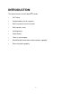
INTRODUCTION The special features of the Protocol™ include: C PID Tuning C Programmable up to 48 segments C Built-in manual reset hi-limit control C Built-in process timer C Self-diagnostics C Digital display C Three (3) event outputs C RS422/RS485 bi-directional communications capability C Recursive profile capability 1
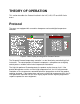
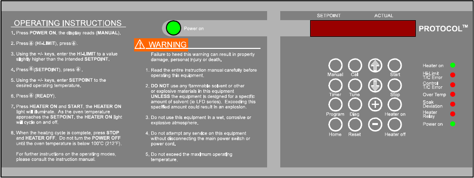
THEORY OF OPERATION This section describes the Protocol installed in the LAC, LAD, LFD and LND Series ovens. Protocol The ovens are equipped with a modular microprocessor based digital temperature controller. Figure 2. Main Display and Keypad on Protocol Control The Despatch Protocol temperature controller is a dual functioning controller/high limit instrument. The control portion of Protocol incorporates a microprocessor to digitally control process variables with minimal temperature fluctuations.
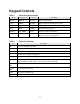
Keypad Controls Table 1 Mode Protocol Keypad Controls Display Code Function Description Manual MANUAL Operation Single setpoint control Timer TIMER Operation Single setpoint control with process timer Program PROGRAM Operation Programmable control with three event outputs Tune TUNE Configure Set instrument parameters Calibrate CAL-MODE Service Performs instrument calibration Diagnostics DIAGNOSE Service Performs instrument thermocouple tests, SSR power level and event output tests
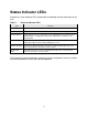
Status Indicator LEDs Protocol has seven indicator LEDs that provide the following relevant information to the user. Table 3 Protocol Indicator LEDs LED Function Power on Lights when the power on pushbutton is pressed. Heater relay Lights when a mode is ready for operation and the heater on key is pressed. Soak Deviation Lights when the process temperature is not held within the user-specified soak deviation limits. The light turns off when the temperature is within the soak deviation limit.
Operating Modes Protocol has three primary modes of operation: the Manual mode, the Timer mode and the Program mode. Manual Mode The Manual mode is a single setpoint control mode that controls the process at the user specified setpoint for an indefinite period of time. The Manual mode controls the oven temperature within close limits as specified by the PID tuning parameters.
Calibration Zero Offset The Calibration Zero Offset (CZO) of Protocol is factory preset and tested for the specified operating conditions. Special instructions for accessing the tune mode to change the CZO are referred to in the Appendix of this manual. Figure 3. CZO Function in Tune Mode The CZO may be useful to make the following small temperature corrections to the control system. C Correction of known sensor calibration errors.
Table 4 Calibration Zero Offset Examples CZO Display Temperature measured by sensor Offset EF Temperature Indication 0.0 4.0 10.0 10.0 -10.0 100 EF 150 EF 150 EF 300 EF 300 EF 0E 2E 5E 20 E -20 E 100 EF 152 EF 155 EF 320 EF 280 EF A more useful formula is one the user can use to calibrate Protocol to match the center of the chamber. This requires a temperature measuring device with its thermocouple junction located at the center of the chamber.
Protocol Hi-Limit Protocol will not let the high limit value drop below the setpoint value. In certain situations, it may be necessary to change the setpoint first and then adjust the high limit value. It will be necessary to reset the hi-limit whenever it has tripped. The hi-limit may be reset by first allowing the oven chamber to cool slightly (or increasing the parameter by several degrees) and pushing the Reset key.
INSTRUCTIONS Start-Up An outline and examples for the Manual mode, Timer mode and Program mode are referenced in the Appendix. A completed typical program worksheet accompanies all programmable event outputs installed at the factory. 1. Start Fan. a. Press Power on pushbutton. You will hear the recirculating fan start. b. Check that the green Power on LED is on. Figure 5.
Manual Mode Startup The following are startup instructions for the Manual mode. 1. Select Manual mode. a. 2. 3. Press the Manual key. MANUAL will be displayed. Enter the high limit temperature. NOTE: For safety reasons, Protocol will not let the operator set the Hi-limit below the setpoint. It may be necessary to adjust the Protocol setpoint first, then adjust the Hi-limit. a. Press – key. HI-LIMIT will be displayed. b. Press – key. c.
Stop The following are stop instructions for the Manual mode. 1. Press the Heater off key. The Heater Relay LED will shut off. 2. Wait for oven temperature to fall below 100E C (212E F). 3. When the Manual mode is complete, press the Reset key to display the final process temperatures. 4. Press the Stop key. 5. Press the Power on pushbutton to turn power off. An example of the Manual mode is referenced in the Appendix.
Timer Mode Startup The following are startup instructions for the Timer mode. 1. Select Timer mode. a. 2. 3. 4. 5. NOTE: During processing the display shows the setpoint on the left and the actual oven temperature on the right. Press Timer key. TIMER will be displayed. Enter the high limit temperature. NOTE: For safety reasons, Protocol will not let the operator set the Hilimit below the setpoint. It may be necessary to adjust the Protocol setpoint first, then adjust the Hi-limit. a. Press – key.
b. Use the + or - keys to select either YES or NO. C Press the - key to display NO and begin timing at ambient. C Press the + key to display YES and begin timing at the following input temperature. c. Press the – key. TEMP and the begin timing temperature will be displayed. d. If YES was selected in step b, use the + or - keys to enter the temperature at which the process timer begins timing. If NO was selected in step b, this setpoint has no bearing on oven operation.
5. Press the Power on pushbutton to turn power off. An example of the Timer mode is referenced in the Appendix of this manual.
Program Mode Startup The following are startup instructions for the Program mode. NOTE: If all event relays are disconnected or no modifications involving event relays have been made to your particular oven, programming the events has no effect on All oven operation. NOTE: profiles entered can be cleared by using the PROF CLR function in the TUNE mode. In any one segment, if the ramp and soak times are zero, Protocol ignores the remaining segments of the profile.
2. c. d. e. f. g. Use the + or - keys to enter the ramp time. Program the events desired during the ramp time. 1. Press – key. EVENTS will be displayed. 2. Press – key for each event. 3. Use the + or - keys to program the event outputs ON or OFF for the ramp period. Program the ramp ending temperature. 1. Press – key. TEMP and the ramp ending temperature will be displayed. 2. Use the + or - keys to enter the desired ramp ending temperature. Program the soak time.
5. 6. 7. 8. Enter the Soak-Deviation. NOTE: The SOAK-DEV limit is also the assured soak limit. This means that the soak times will not begin until the process temperature is within the SOAKDEV parameter. a. Press – key until SOAK-DEV is displayed. b. Press a key. The symbol +/- will be displayed. c. Use the + or - keys to enter the soak deviation limit. Enter the next profile to continue to, or end profile. a. Press – key. GOTO will be displayed. b.
Run The following are run instructions for the Program mode. NOTE: When in the Program mode, pressing the Start key will display the time remaining in the cycle (TRHHMMSS). Pressing the Reset key will display the profile number, segment number and the loops (REPEAT TIMES) remaining. 1. Press Home key until PROGRAM is displayed. 2. Press – key until PRO-1 is displayed. 3. Make sure the correct starting profile is entered by pressing + or -. 4. Press the • key until READY is displayed. 5.
APPENDIX Special Instructions The Protocol has been preset and tested at the factory for normal operating conditions. In most applications, it will not be necessary to alter the oven's settings. This section contains additional information and reference for special operating conditions.
Control Instrument Tune Mode Various functions of the control instrument are set by parameters in the tune mode. To access the tune mode, it is necessary to enter the proper code. 1. Press Tune key. The display reads TUNE. 2. Press – key. CODE *** will be displayed. 3. Enter +, -, -, +, -, +. PID TUNE will be displayed. The PID tuning parameters may be entered. The units are listed below.
Table 6 Tuning Outline Display Description TUNE CODE PID TUNE P-1 I-1 D-1 DEG SPL CZO DIS BEEP PF-RECVR Selects tune mode. Enter + - - + - + Enter tuning parameters. Proportional band in degrees (+/- keys). Reset in seconds/repeat (+/- keys). Rate in degrees/second keys). Select EC or EF (+/- keys). Setpoint limit, set to maximum temperature of oven (+/- keys) Calibration zero offset -99.9 to 99.9 (+/- keys). Time set in MMSS (minutes/seconds) or HHMM (hours/minutes). Select beep on or off (+/- keys).
Tuning Worksheet In most applications it is not necessary to alter tuning parameters. To enter the tune mode, press the Tune key. Tune will be displayed. Press – and enter +, -, -, +, -, +. Using the – key and the +/- keys, enter the desired settings. Press Home when finished.
Calibration Mode Protocol has been tested and calibrated at the factory. Under normal operating conditions recalibration should not be necessary. However, if the instrument does not comply with known standards recalibration may be necessary. Calibration Instructions We recommend using a certified analog thermocouple simulator/calibration source with less than ±1E F noise.
All errors must be cleared to perform calibration. Any active error will inhibit the calibration function. To clear a Hi-Limit control error [HL ERROR] caused by lost of calibration (Hi-Limit indication of 500E C or 932E F in the diagnostic mode): 1. Increase the Hi-Limit setpoint to 500E C or 932E F. 2. Press the Reset key. 7. Loosely fasten the Protocol controller to the oven. 8. Re-connect AC power to the oven. 9. Press the Power on pushbutton to energize oven. 10. Press the Tune key.
Tune Mode Parameter Calibration NOTE: ### or ##.# represents a numeric value or parameter. Press Display Actual Setting Press Adjustable Range – key P-1 ### 5 + or - keys 0E C to 500E C 32E F to 932E F – key I-1 ### 30 + or - keys 0 to 999 seconds/repeat – key D-1 ### 0 + or - keys 0 to 999 degrees/second C C + key for C or - key for F. – key DEG - – key SPL - ### maximum designed operating temperature¹ + or - keys 0E C to 500E C 32E F to 932E F – key CZO - ##.
15. Apply a 250E F signal to the high limit thermocouple input: a. Connect the piece of type J thermocouple lead wire, wired to the High Limit T/C terminals, to a thermocouple simulator. b. Set the simulator to output a type J thermocouple signal. c. Twist together or jumper the piece of type J thermocouple lead wire, wired to the Control T/C terminals. This creates a junction and prevents a Control sensor error [S-T/C ERR] caused by an open thermocouple.
22. Press the following key sequence: -, -, +. The display now reads SCAL 450. 23. Adjust the simulator to supply a 450E F signal. Wait for 30 seconds while the control stabilizes. 24. Press the following key sequence: +, +, -. The display now reads SENS 450. 25. To verify proper calibration, adjust the simulator to supply a 350E F signal. Within 30 seconds, the display should stabilize and read SENS 350. 26. Press the Manual key. The display reads [MANUAL].
Calibration Recovery The Protocol control has a factory calibration recovery feature. This feature allows the operator to restore the Protocol to an operational condition should a calibration error occur. The Factory Calibration Recovery feature should only be used as a temporary fix until a proper calibration procedure utilizing a calibration source can be performed. Only a complete calibration will restore the Protocol to an optimum performance level.
Diagnostics Mode The diagnostics mode is provided to give certain relative information about Protocol. The following table gives an outline of the diagnostics mode. Display Description DIAGNOSE Select Diagnostics mode. SSR Protocol SSR output level.
Power Failure In the event that the power supplied to Protocol is insufficient at any point during a running mode, the display will read PWR-FAIL. In the tune mode the user can choose the Power Fail Recovery mode from Stop, Resume and Hold. To restart after a power failure in the hold mode, press the Start key to resume oven operation. Otherwise, press the Reset key to clear the PWR-FAIL display. Do not shut off the power during a running mode.
Programming Examples and Outline The following examples show a step by step procedure for programming Protocol in the Manual, Timer and Program modes. Example 1 covers the Manual mode and example 2 covers the Timer mode. A detailed outline covers the Program mode with a programming worksheet and examples 3-5 following the outline. Example 1 - Manual Mode NOTE: Do not turn the power off until the oven temperature is below 100EC (212EF). NOTE: EF is selected in the tune mode. Control the process at 250EF.
Example 2 - Timer Mode NOTE: EC and HHMM (hours/minutes) is selected in the tune mode. Control the process at 200EC for three hours and 15 minutes with the timer beginning at 195EC. Protocol will stop automatically when run in Timer mode.
Program Mode Program Mode Outline Display PROGRAM Description Select Program mode. Hi-Limit for Program mode Hi-Limit Enter high limit temperature (+ or - keys). HL PROFILES PROSEGRAMP EVENTS E-1 E-2 E-3 Enter profile number (1-8).
C The profile number is manually entered using the + or - keys. C Six segments exist for each profile. C If the ramp time and soak time for any one segment is zero, Protocol ignores the remaining segments. C The REPEAT TIMES command is the number of times to execute the profile being programmed. C The HOLD command is contingent on the final segment of the last profile to be run only. C A soak time will not begin until the actual temperature is within the soak-deviation limit. (Assured soak limit).
Program Worksheet The program worksheet serves as a guide to the input parameters for the program mode. Figure 7.
Example 3 - Program Mode Follow the characteristic curve listed below. NOTES: HHMM (hours/minutes) and EC selected in the tune mode. No event outputs are being used. SoakDeviation limit = ±7EC (also assured soak limit). Hold at last setpoint. Ramp and soak times of zero in any one segment ignores remaining segments. Figure 8.
Example 4 - Program Mode Autostart the oven after two hours and follow the characteristic curve below. NOTES: MMSS (minutes/seconds) and EF selected in the tune mode. Event 1 wired properly for autostart, events 2 - 3 are not used. No hold at last setpoint. Soak-Deviation = ±5EF (also assured soak limit). Minimum operating temperature is 70EF. Figure 9.
Example 5 - Program Mode Complete characteristic curve five times. NOTES: HHMM (hours/minutes) and EC selected in the tune mode. No events used. SoakDeviation = 10EC (also assured soak limit). Minimum operating temperature = 50EC. Ramp and soak times of zero in any one segment ignores remaining segments. Figure 10.
Troubleshooting PROBLEM/ SYMPTOM Erratic temperature control Temperature will not reach the Setpoint PROBABLE CAUSE SUGGESTED CORRECTIVE ACTION The controller typically has a proportion band (PB) of 5°F.
PROBLEM/ SYMPTOM Temperature runaway - heater will not turn "OFF" PROBABLE CAUSE Shorted SSR Relay Disconnect the one of the SSR leads (SSR terminal #3 or #4). If the heater stays "ON", Replace SSR. Defective controller If heater turns "OFF", controller may be defective (check DIAGNOSTICS MODE).
PROBLEM/ SYMPTOM Control or Hi-limit readout displays 500°C or 932°F PROBABLE CAUSE Loss of calibration SUGGESTED CORRECTIVE ACTION Perform calibration.