E-102 p.n. 143896 Modbus User's Programming Manual For Despatch ProtocolTM Plus A-51643 Rev.
Chromalox Instruments and Controls Revision History Rev. Date Description 0 10/6/1998 Original Release 1 01/25/1999 Major revisions to match tested software. 2 02/12/1999 Corrected temperature readout descriptions to 1 F from 0.1 F. Corrected misc. typos. Removed front panel security code holding register. Moved communication security code holding register to address 0. 3 03/22/1999 Corrected figure references in communication card setup sections.
Chromalox Instruments and Controls Table of Contents 1 2 3 4 OVERVIEW ........................................................................................................................................................1 1.1 PURPOSE .......................................................................................................................................................1 1.2 CONVENTIONS AND DEFINITIONS ...................................................................................
Chromalox Instruments and Controls 5.1 FUNCTION SET OVERVIEW .......................................................................................................................... 20 5.2 REGISTER AND I/O FUNCTION SET DESCRIPTION FOR PROTOCOL TM 5.2.1 [01] Read Outputs ................................................................................................................................. 21 5.2.2 [02] Read Input Discretes ..................................................................
Chromalox Instruments and Controls 6.7.1 7 The Byte Count Field ............................................................................................................................. 41 PROGRAMMING EXAMPLE AND GENERAL HINTS ............................................................................ 42 7.1 CODE EXAMPLE .......................................................................................................................................... 42 7.
Chromalox Instruments and Controls A-51643 Rev.
Chromalox Instruments and Controls 1 1.1 Overview Purpose This document provides all application specific information necessary for developing a Modbus Master application program for interfacing with the ProtocolTM Plus slave controller. The assumption is made that the programmer has at least an intermediate understanding of the Modbus Protocol. Only limited information is presented here regarding the Modbus Protocol specifications. Below is a list of relevant Modbus Protocol documents.
Chromalox Instruments and Controls 2 2.1 Communications Specifications Support Specifications Device Support: Slave only. Slave ID Code (Identifies Product Line): 1. Transmission Mode: RTU mode only. Communication Medium: RS232, RS422, or RS485. Address Support: 1 – 247. Baud Rate: 2400, 4800, 9600, 19.2K, 38.4K Parity: None, Even, or Odd. 2.2 Timing Specifications Message Framing: Silent period of at least 3.5 character times before the first character and after the last character of the message.
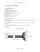
Chromalox Instruments and Controls Figure 2: RS422A Wiring (4 wire) Rcv + 1 Rcv + 2 14 Rcv - 2 Rcv - 7 2 Xmit + 3 Xmit + 3 16 Xmit - 4 Xmit - 4 3 Gnd 5 Gnd 5 7 Protocol™ Plus Connector Xmit + (b) Master Device Xmit – (a) (Pin #‘s based on RS-530 Rcv + (b) standard; may vary by Rcv – (a) device) Gnd Protocol™ Plus DB-9 Connector DB-25 Figure 3: RS485 Wiring (2 wire) 14 2 T/R + T/R Gnd 3 4 5 Protocol™ Plus Connector 2.
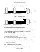
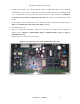
Chromalox Instruments and Controls 3. Looking into the back of the controller with the connector terminal strips at the bottom, install the communication card onto the two 5 pin headers on the rear circuit board. Be sure the jumper blocks on the communication card are positioned toward the bottom of the controller. See Figure 4: Controller Rear View with Communication Card (Left). Be sure the card is seated firmly onto the headers. 4.
Chromalox Instruments and Controls 2.4.2 Communication Card Jumper Settings 1. Turn off power to the controller. 2. Remove the back cover of the controller (if it is not already removed) by removing the two screws at the top of the unit. 3. Set the jumpers on the communication card for the desired serial communication interface based on Figure 5: Communication Card (0113-10175) Jumper Settings. 4. Reinstall the back cover. 5. Reapply power to the controller.
Chromalox Instruments and Controls 3 3.1 Register and I/O Mapping Unmapped and Reserved Registers Reserved and NA registers will be read as zero with no exception error being generated. Thus, the host can request data from multiple addresses with gaps between and still receive a valid response. Illegal and undefined register address blocks will always generate an illegal data address exception.
Chromalox Instruments and Controls Table 4: ProtocolTM Plus Discrete Output Address Map Data Address Hex Address Description 0 $0000 Relay Output 1 0 1 $0001 Relay Output 2 0 2 $0002 Relay Output 3 0 3 $0003 Relay Output 4 0 4 -- 7 $0004 -- $0007 Illegal, Reserved for future inputs 0 8 -- 65535 $0008 - $FFFF Undefined, available for application assignment 0 A-51643 Rev.
Chromalox Instruments and Controls 3.5 Input Register Assignments Input registers are intended for read only information and functions that cannot or should not be controlled remotely. Much status information is mapped as holding registers so that operations can be controlled remotely. Examples are control output commands, ramp/soak status (run, hold, stop), and ramp/soak program number.
Chromalox Instruments and Controls 149 95 Events Status 0 - $F 0 Bits 0-3 = Events 1-4. Bit value: 0 = Off, 1 = On 150 96 151 97 Cycle Complete Status 0, 1 0 0 = Off, 1 = On Audible Annunciator Status 0, 1 0 0 = Off, 1 = On 0 0 0 0 152 -- 155 98 -- 9B Reserved, available to application 156 – 157 9C – 9D Reserved for factory use 158 -- 159 9E – 9F N/A A/D Input Registers 160 -- 165 A0 -- A5 Reserved for factory use 166 -- 167 A6 -- A7 Illegal, Reserved standard reg.
Chromalox Instruments and Controls 3.6 Holding Register Assignments Holding registers are intended for information and functions that can be read or written. Each holding register has a corresponding internal memory variable in the slave device. This association is shown in the address map table.
Chromalox Instruments and Controls 31 1F Control Type 32 – 34 20 – 22 35 23 Auto Tune Enable 36 24 37 25 38 – 39 26 – 27 40 28 Power Fail Recovery Control[PwrFRec] 1 or 2 (Note 1) 0=Stop, 1=Restart, 2=Hold, 3=Resume Recovery Time Limit Control[PFRTime] 1 or 2 (Note 1) 00h00m to 99h59m NA Control[Ctrl] 1 or 2 (Note 1) 0 = Heat, 1 = Cool, 2 = Heat/Cool.
Chromalox Instruments and Controls 421 1A5 Segment 4 Ramp Event 1-4 Setup Seg-4 Ramp[Event1-4] 422 1A6 Segment 4 Soak Temp Seg-4 Soak[Temp] 1 or 2 (Note 1) read/written as xxxx deg. F.
Chromalox Instruments and Controls 774 306 Sunday Run Mode Auto Start Sun[Mode] 1 or 2 (Note 1) 0=Off, 1=Manual, 2=Timer, 3-10=Profile 1-8 775 307 776 308 Sunday Run Time Auto Start Sun[Time] 1 or 2 (Note 1) 00h00m to 23h59m Monday Run Mode Auto Start Mon[Mode] 1 or 2 (Note 1) 0=Off, 1=Manual, 2=Timer, 3-10=Profile 1-8 777 778 309 Monday Run Time Auto Start Mon[Time] 1 or 2 (Note 1) 00h00m to 23h59m 30A Tuesday Run Mode Auto Start Tue[Mode] 1 or 2 (Note 1) 0=Off, 1=Manual, 2=Timer, 3-
Chromalox Instruments and Controls 1152 -- 1159 480 -- 487 Reserved for factory use 1160 -- 1183 488 -- 49F Illegal, Available to application 1184 -- 1188 4A0 -- 4A4 Reserved for factory use 1189 -- 1199 4A5 -- 4AF Illegal, Available to application 1200 -- 1279 4B0 -- 4FF Illegal, Reserved for standard reg. Reserved for future standard assignments.
Chromalox Instruments and Controls 4 Application Operations This section defines application operations in ProtocolTM Plus controller and how they are achieved through Modbus. 4.1 Security Level and Discrete Inputs, Discrete Outputs, and Register Access Access to discrete I/O and registers addresses are guarded via a security level. The communications security code holding register ($0000) contains the current security setting for accessing data in the controller through the communications port.
Chromalox Instruments and Controls An example is the Manual Setpoint and Manual High Limit Setpoint holding registers. If the registers are currently set to 500 F and 509 F respectively, then a multiple write of 300 F and 350 F respectively will fail. During data verification, the high limit value of 350 F is invalid because the setpoint is set to 500 F. A single write of 300 F to Manual Setpoint followed by a single write of 350 F to Manual High Limit Setpoint will work. 4.
Chromalox Instruments and Controls REGISTER ADDRESS 4.
Chromalox Instruments and Controls 4.6 Event Setup Values For Manual, Timer, and Profile events setup, the corresponding holding register represents a binary pattern that determines each event output state. Bits 0-3 of the holding register value represent Event outputs 1-4 respectively. A bit value of 0 sets the event output to be off, while a bit value of 1 sets the output to be on. 4.
Chromalox Instruments and Controls 1. Send an individual function code 08, sub-function 10 queries (clear communication counters) to each slave on the network. 2. Perform desired broadcast functions. 3. Send an individual function code 08, sub-function 14 queries (return slave message count) to each slave on the network. 4. If the number of processed messages in each slave matches the number of broadcasts sent then the broadcast messages were sent reliably. 4.
Chromalox Instruments and Controls 5 Function Set Details This section details the Modbus functions supported in the ProtocolTM Plus controller. 5.
Chromalox Instruments and Controls 15 Return Slave No Response Count Number of messages addressed to the slave for which no response was returned. 18 Return Bus Character Overrun Count Number of overrun and framing errors. Table 10 ProtocolTM Plus Exception Code Set Exception Code 01 Description Illegal Function Comments The function code received is not valid or is not supported. 02 Illegal Data Address The data address received is invalid or is not accessible due to security setting. 03 5.
Chromalox Instruments and Controls Response The output status in the response is packed as one output per bit of the data field. Status is indicated as 0 = Off, 1 = On. The LSB of the first data byte contains the output addressed in the query. The other outputs follow toward the high order end of this byte, and from low order to high order in subsequent bytes.
Chromalox Instruments and Controls Number of outputs hi $00 Number of outputs lo $07 CRC $---- Response The input status in the response message is packed as one input per bit of the data field. Status is indicated as 0 = Off, 1 = On. The LSB of the first data byte contains the input addressed in the query. The other inputs follow toward the high order end of this byte, and from low order to high order in subsequent bytes.
Chromalox Instruments and Controls Number of registers hi $00 Number of registers lo $03 CRC $---- Response The register data in the response message are packed as two bytes per register (one word). For each register, the first byte contains the high order bits and the second contains the low order bits.
Chromalox Instruments and Controls Starting address lo $09 Number of registers hi $00 Number of registers lo $01 CRC $---- Response The register data in the response are packed as two bytes per register (one word). For each register, the first byte contains the high order bits and the second contains the low order bits. Example response: Field Name Data Slave address $11 Function $04 Byte count $02 Data (register 10 hi) $00 Data (register 10 lo) $23 CRC $---- 5.2.
Chromalox Instruments and Controls Field Name Data Slave address $0E Function $06 Register address hi $00 Register address lo $01 Data hi $00 Data lo $03 CRC $---- Response The normal response is an echo of the query, returned after the register has been written. Example response: Field Name Data Slave address $0E Function $06 Register address hi $00 Register address lo $01 Data hi $00 Data lo $03 CRC $---- 5.2.6 [16] Write Multiple Registers Class 0 command.
Chromalox Instruments and Controls high order bits and the second byte the low order bits. Next, the actual number of data bytes is transmitted (one byte). The requested values are specified in the query data field in two bytes (one word) per register. The first byte represents the high order bits and the second byte represents the low order bits of the register value. Example: Request to preset two registers starting at register 5 to the values of 10 and 258 respectively in slave device 14.
Chromalox Instruments and Controls 5.3 Diagnostics and Support Description for ProtocolTM Plus All of the diagnostic and support functions are unclassified commands that tend to be application dependent. The Modbus diagnostic function provides a series of tests and information exchange for checking the integrity of the controller, the communication link, and the status of the controller. Broadcast is not supported. 5.3.
Chromalox Instruments and Controls Query Response Field Name Data Field Name Data Slave address $02 Slave address $02 Function $08 Function $08 Sub-function hi $00 Sub-function hi $00 Sub-function lo $00 Sub-function lo $00 Data hi $AA Data hi $AA Data lo $55 Data lo $55 CRC $---- CRC $---- 5.3.1.2 [08 01] Restart Communications Option The slave is reset, its communication port initialized and restarted, and all of its communications event counters cleared.
Chromalox Instruments and Controls Table 11: ProtocolTM Plus Diagnostic Register Bit Assignment Bit # Description 0 NA 1 NA 2 EEPROM Data Error 3 NA 4 NA 5 NA 6 NA 7 A/D 8 Not Used – Loop Error 9 Not Used – Tune Error 10 Not Used -- Available for Application Specific Support 11 Not Used -- Available for Application Specific Support 12 Not Used -- Available for Application Specific Support 13 Not Used -- Available for Application Specific Support 14 Not Used -- Available for Ap
Chromalox Instruments and Controls addressed to the slave are monitored, but no action is taken and no responses sent. The Restart Communications Option function is the only command that will bring the slave out of Listen Only Mode. Example: Force slave device 23 into Listen Only Mode. Query Field Name No Response Data Slave address $17 Function $08 Sub-function hi $00 Sub-function lo $04 Data hi $00 Data lo $00 CRC $---- 5.3.1.
Chromalox Instruments and Controls Query Field Name Response Data Field Name Data Slave address $09 Slave address $09 Function $08 Function $08 Sub-function hi $00 Sub-function hi $00 Sub-function lo $0C Sub-function lo $0C Data hi $00 Data hi $00 Data lo $00 Data lo $07 CRC $---- CRC $---- 5.3.1.
Chromalox Instruments and Controls Function $08 Function $08 Sub-function hi $00 Sub-function hi $00 Sub-function lo $0E Sub-function lo $0E Data hi $00 Data hi $00 Data lo $00 Data lo $6C CRC $---- CRC $---- 5.3.1.9 [08 15] Return Slave No Response Count The response data field returns the quantity of messages addressed to the slave for which it returned no response since its last reset or clear counters command. No response due to errors are not counted.
Chromalox Instruments and Controls Data hi $00 Data hi $00 Data lo $00 Data lo $03 CRC $---- CRC $---- 5.3.2 [17] Report Slave ID Requests the slave to return its ID code. The ID code identifies the product line of which the slave is a member. The Slave ID for ProtocolTM Plus is 1. Besides the ID code, the slave‘s software version number is also returned as an ASCII string. The version number will be sent in the format ―VXX.X‖.
Chromalox Instruments and Controls 5.4 Exception Response Description Except for broadcast messages, when a master device sends a query to a slave it expects a normal response. One of four possible events can occur from the master query: 1. If the slave device receives the query without a communication error, and can handle the query normally, it returns a normal response. 2. If the slave does not receive the query due to a communication error, no response is returned.
Chromalox Instruments and Controls No. of Registers Lo $08 CRC $---- Exception Response Format Field Name RTU Example Data Description Slave Address $06 Slave number 6 Function $81 Read output status with MSB set Exception Code $02 Illegal Data Address Exception code CRC $---- 5.4.1 [01] Illegal Function The function code received in the query is not an allowable action for the slave. 5.4.
Chromalox Instruments and Controls 6 Modbus Protocol Quick Reference This section highlights portions of the Modbus Protocol that may provide useful quick reference information to the programmer as it applies to the ProtocolTM Plus slave implementation. 6.1 Protocol Format The master‘s query contains the device address (or broadcast address), a function code defining the requested action, any data to be sent, and an error-checking field.
Chromalox Instruments and Controls Without Parity Checking Start 6.2.3 D0 D1 D2 D3 D4 D5 D6 D7 Stop Stop Error Checking Field 16-bit CRC 6.2.4 Message Framing In RTU mode, messages start with a silent interval of at least 3.5 character times. This is most easily implemented as multiple idle character times at the baud rate chosen for the network. The first field transmitted is the device address. Following the last transmitted character, a similar interval of at least 3.
Chromalox Instruments and Controls 6.5 Data Field The data field contains additional information that the slave must use to take action defined by the function code. If no error occurs, the data field of a response from the slave contains the data requested. If an error occurs, the filed contains an exception code that the master application can use to determine the next action to be taken. The data field can be nonexistent in certain kinds of messages.
Chromalox Instruments and Controls Figure 6 CRC Flowchart Start CRC16 = $FFFF Grab first byte of message CRCLO = CRCLO Data N=0 Logical Shift Right CRC16 (0 CRC16 C) 1 CRC16 = CRC16 Test C $A001 0 N = N+1 No N = 8? Yes No Get next message byte Last message byte? Yes Stop 6.7 Field Contents in Modbus Messages The following tables show examples of a Modbus query and a normal response in RTU mode. A-51643 Rev.
Chromalox Instruments and Controls Query Field Name RTU Example Data Description Header > 3.5 idle characters Start characters Slave Address $06 Slave number 6 Function $03 Read multiple registers Starting Address Hi $00 Start reading at holding register 108 Starting Address Lo $6B No. of Registers Hi $00 No. of Registers Lo $03 CRC Lo $75 CRC Hi $A0 Trailer > 3.
Chromalox Instruments and Controls 7 Programming Example and General Hints This section provides an example of Microsoft Visual BasicTM code used to communicate with a ProtocolTM Plus controller. In addition, some general programming hints are provided. 7.1 Code Example The following Visual Basic™ code example assumes that an MSComm control named ‗comMain‘ has been placed on a form named ‗frmComm‘. The form also contains a command button named ‗Command1‘, and a text box named ‗Text1‘.
Chromalox Instruments and Controls 'initialize the CRC register: CRCValue = 65535 For i = 1 To MLength 'this routine is called for each character of a message CRCValue = CRCValue Xor CInt(Asc(Mid(MBuffer, i, 1))) 'for each bit in the new character, 'do this loop: For j = 1 To 8 'determine if LSB is now a 1: LsbSet = ((CRCValue And 1) = 1) 'shift the crc (buffer) one bit to the right: CRCValue = Int(CRCValue / 2) 'if LSB was a 1, If LsbSet Then 'XOR buffer value with the CRC polynomial: CRCValue = CRCValue
Chromalox Instruments and Controls 'set the Settings to select Baud Rate, Parity, Data bits, and Stop bits. 'Note that Baud Rate and Parity must match the Controller's settings, 'always use 8 Data bits and 2 Stop bits. frmComm.comMain.Settings = "38400,N,8,2" 'set other parameters: frmComm.comMain.InputLen = 0 frmComm.comMain.Handshaking = comNone frmComm.comMain.InputMode = comInputModeText frmComm.comMain.InBufferSize = 1024 frmComm.comMain.RThreshold = 1 frmComm.comMain.InputLen = 0 frmComm.comMain.
Chromalox Instruments and Controls CRCWord = GetCRC(TxMessage) 'add the CRC bytes to the message: TxMessage = TxMessage & Chr(CRCWord - Int(CRCWord / 256) * 256) TxMessage = TxMessage & Chr(Int(CRCWord / 256)) 'clear status text display: Text1 = "" 'clear the receive data buffer: RxMessage = "" 'send the message out the COM port: frmComm.comMain.
Chromalox Instruments and Controls 'can be calculated before the TxMessage is sent, when RxMessage contains 'the expected message length, then reception is complete.
Chromalox Instruments and Controls 7.2 Additional Communications Troubleshooting Hints Communications problems occur primarily due to physical wiring problems or mismatched settings. It is important to verify that the ProtocolTM Plus controller‘s Communication Card is properly installed, and its jumpers are properly set to match the wiring option used (RS-232, RS-422, or RS-485).