
Manual


Chromalox Instruments and Controls
A-51643 Rev. 6 10/06/03 4
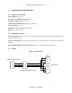
3. Looking into the back of the controller with the connector terminal strips at the bottom, install the
communication card onto the two 5 pin headers on the rear circuit board. Be sure the jumper blocks
on the communication card are positioned toward the bottom of the controller. See Figure 4:
Controller Rear View with Communication Card (Left). Be sure the card is seated firmly onto the
headers.
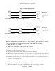
4. Set the jumpers on the communication card for the desired serial communication interface based on
Figure 5: Communication Card (0113-10175) Jumper Settings.
5. Reinstall the back cover.
6. Wire the communication connections on the rear of the unit for the desired serial communication
interface based on Figure 1: RS232 Wiring, Figure 2: RS422A Wiring (4 wire), or Figure 3:
RS485 Wiring (2 wire).
7. Reapply all power connections to the controller.
Figure 4: Controller Rear View with Communication Card (Left)