
Manual


Chromalox Instruments and Controls
A-51643 Rev. 6 10/06/03 8
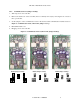
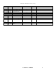
3.5 Input Register Assignments
Input registers are intended for read only information and functions that cannot or should not be
controlled remotely. Much status information is mapped as holding registers so that operations can be
controlled remotely. Examples are control output commands, ramp/soak status (run, hold, stop), and
ramp/soak program number.
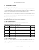
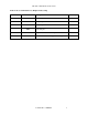
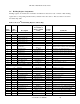
Table 5: Protocol
TM
Plus Input Register Address Map
Data
Address
Hex
Address
Description
Page[menu]
Association or
Range
Security
Level
Comments
Control Loop Input Registers
0
0
PV
Sensor range
0
read as xxxx deg. F
1
1
Active SP
Sensor range
0
read as xxxx deg. F
2
2
Active Hi Limit SP
Sensor range
0
read as xxxx deg. F
3
3
PV Status
-1, 0, 1
0
-1 = underrange, 0 = in range, 1 = overrange
4
4
NA
0
0
5
5
Hi Limit PV
Sensor Range
0
read as xxxx deg. F
6
6
Hi Limit PV Status
-1, 0, 1
0
-1 = underrange, 0 = in range, 1 = overrange
7
7
Control Output Command
0 - 100.0
0
value has an implied decimal pt. of 1
8
8
Hi Limit Output
0, 1
0
0 = Off, 1 = On
9
9
Max Hi Limit SP
Control[Hi-Lim SP]
0
read as xxxx deg. F
10
A
NA
0
0
11
B
PV Max
Sensor Range
0
read as xxxx deg. F
12
C
PV Min
Sensor Range
0
read as xxxx deg. F
13
D
Reserved for factory use
14
E
Reserved for factory use
15
F
Reserved for factory use
16 -- 127
10 -- 7F
Illegal, Reserved standard reg.
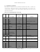
Timer/Profile Input Registers
128
80
Segment Number
1-99
0
Current segment number
129
81
Timer/Ramp/Soak Interval Time
Remaining
00:00 - 99:59
0
Time remaining in ramp/soak interval
130
82
Segment Loops Remaining
0 - 99
0
Number of loops remaining in the ramp/soak program.
131
83
Ramp/Soak Interval Indicator
0, 1
0
0 = ramp interval of segment, 1 = soak interval of
segment
132 -- 143
84 -- 8F
Illegal, Available to application
Global Input Registers
144
90
Terminal Temp (CJC)
Ambient Range
0
read as xxx.x deg. F
145
91
N/A
0
0
146
92
Reset Counter
0 - $FFFF
0
Number of processor resets.
147
93
Power Down Counter
0 - $FFFF
0
Number of power down interrupts.
148
94
Alarms Status
0 - $F
0
Bits 0-3 = Alarms 1-4. Bit value: 0 = Off, 1 = On