
Manual


Chromalox Instruments and Controls
A-51643 Rev. 6 10/06/03 3
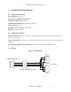
Figure 2: RS422A Wiring (4 wire)
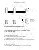
Figure 3: RS485 Wiring (2 wire)
2.4 Communication Card Installation and Jumper Settings
WARNING
Electronic Components are extremely sensitive to static electricity. Before opening the controller
case, read and follow the precautions below to prevent damage from static electricity.
1. Turn off power to the controller.
2. Touch a bare metal surface on the exterior of the controller.
3. Disconnect the power connection from the controller or unplug from the power source.
Also follow these static electricity precautions:
Avoid static-causing surfaces while working with electronic components.
Remove parts from their anti-static bags only when ready for use. Do not lay parts on the outside of
the anti-static bag because only the inside provides protection.
Hold circuit boards by their edges or any metal mounting hardware. Avoid touching components or
connectors on the circuit boards.
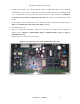
2.4.1 Communication Card (0113-10175) Installation
1. Turn off power to the controller.
2. Remove the back cover of the controller by removing the two screws at the top of the unit.
Xmit +
Rcv -
Gnd
3
2
5
Protocol™ Plus DB-9 Connector
Rcv +
7
Xmit -
4
Master Device
(Pin #‘s based on RS-530
standard; may vary by
device)
Xmit – (a)
Rcv + (b)
Gnd
2
3
7
DB-25
Xmit + (b)
16
Rcv – (a)
14
Xmit +
Rcv -
Gnd
3
1
5
Rcv +
2
Xmit -
4
Protocol™ Plus Connector
T/R +
Gnd
3
5
Protocol™ Plus DB-9 Connector
T/R -
4
T/R +
Gnd
3
5
T/R -
4
Protocol™ Plus Connector
Master Device
(Pin #‘s based on RS-530
standard; may vary by
device)
Xmit – (a)
Rcv + (b)
Gnd
2
3
7
DB-25
Xmit + (b)
16
Rcv – (a)
14