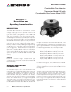
Instructions 95-8472 Combustible Gas Detector Transmitter Model 505 with Combustible Gas Sensor Model CGS 3.
Table Of Contents SAFETY MESSAGES. . . . . . . . . . . . . . . . . . . . . . . . . . . . . . . . . . . . . . . . i Section I - Description and Operating Characteristics DESCRIPTION . . . . . . . . . . . . . . . . . . . . . . . . . . . . . . . . . . . . . . . . . . . . 1 Sensor. . . . . . . . . . . . . . . . . . . . . . . . . . . . . . . . . . . . . . . . . . . . . . . .
Safety Messages IMPORTANT Be sure to read and understand the entire instruction manual before installing, operating or servicing the gas detection equipment. CAUTION To ease installation and future removal, ensure that all junction box covers and sensor threads are properly lubricated. If the need arises for additional lubrication, use either Lubriplate grease (P/N 102868-001) or Teflon tape for sensor threads. Avoid the use of silicone grease.
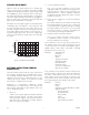
INSTRUCTIONS Combustible Gas Detector Transmitter Model 505 with Combustible Gas Sensor Model CGS Section I — Description and Operating Characteristics DESCRIPTION The Model 505 Transmitter is used with one constant voltage catalytic gas sensor to provide a linear 4 to 20 mA output signal corresponding to a 0 to 100% LFL gas concentration (see Figure 1). Intrusive calibration and sensor sensitivity checks are performed using a standard digital voltmeter (not provided).
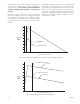
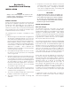
SENSOR RESPONSE 2. Corrosive liquids and vapors. This can occur when substances such as H2S, (hydrogen sulfide), Cl2 (chlorine) or HCl (hydrochloric acid) are present. A dust cover may provide some limited protection. Routine calibration frequency should be increased in applications where corrosive materials are present. Figure 2 shows the typical response of a catalytic gas sensor to various levels of methane. Note that a reading of 40% LFL will be given at 2.0% by volume methane and also at 80.
A brief exposure to any of these materials may temporarily increase the sensitivity of the sensor due to etching of the catalytic surface. This practice is not recommended, since it is unreliable and may give a false sense of security. The degree of damage to a catalytic sensor is determined by the type of contaminant, its concentration in the atmosphere, and the length of time the sensor is exposed.
SPECIFICATIONS TEMPERATURE RANGE— Operating: –40°F to +167°F (–40°C to +75°C). Storage: –67°F to +185°F (–55°C to +85°C). TRANSMITTER INPUT VOLTAGE— With signal loop impedance option A: With signal loop impedance option B: HUMIDITY RANGE— 0 to 99% RH, non-condensing. 10 to 30 Vdc 17 to 30 Vdc. Linear, regulated, filtered 24 Vdc power source is recommended. RFI/EMI IMMUNITY— Less than ± 0.
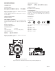
CATALYTIC SENSOR CALIBRATION CYCLE— 30 days after initial calibration and every 90 days thereafter, or as required by the application and environment. TEMPERATURE RANGE— Operating: –67°F to +257°F (–55°C to +125°C). Performance: –40°F to +167°F (–40°C to +75°C). DIMENSIONS— See Figure 5. HUMIDITY RANGE— 0 to 99% RH, non-condensing. CERTIFICATION— RESPONSE TIME— 50% full scale in 3.8 seconds with 100% LFL applied, 5% by volume. 90% full scale in 8.4 seconds with 100% LFL applied, 5% by volume.
Section II — Installation and Startup 7. Exposure to excessive heat or vibration can result in premature failure of electronic devices and should be avoided if possible. Shielding the transmitter from intense sunlight will reduce solar heating and enhance the service life of the unit. INSTALLATION IMPORTANT All diffusion-based gas sensors including the catalytic gas sensor used with the Model 505 must contact the target gas in order to provide an accurate gas measurement and response.
A continuous, three conductor cable with an overall foil shield must be used with the sensor separation kit. The cable shield drain wire should be cut back and insulated within the sensor junction box and connected to earth ground at the transmitter junction box. Failure to use a shielded cable or properly ground the shield is likely to result in nuisance alarms caused by EMI/RFI problems.
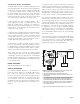
CONTROLLER 4 TO 20 MA SIG RED WHT – + – + BLK SEN + SOR – 24 VDC TRANSMITTER LOCATION NOTES 1. SHIELDED SENSOR WIRING CABLE REQUIRED. CONNECT KEYED SENSOR PLUG TO PIN CONNECTOR RED WHT 2. GROUND SENSOR WIRE SHIELD AT TRANSMITTER END ONLY. BLK 3. SHIELDS SHOULD BE STRIPPED BACK WITHIN JUNCTION BOXES. 4. TERMINAL CONNECTOR REQUIRED FOR SENSOR CONNECTION 4. (PROVIDED WITH SENSOR TERMINATION BOX).
ZERO/SPAN SWITCH SENSOR VOLTAGE ADJUST CAL/NORM SWITCH CALIBRATE LED 4 MA ADJUST 8. Insert the plug-in connector into the power and signal wire receptacle on the Model 505 transmitter board. Reconnect the power and signal cable shield drain wire (if used) as previously installed. Route any excess power and signal wiring inside the junction box around the perimeter of the Model 505 transmitter board to allow easy access to the switches and potentiometers. ZERO ADJUST SPAN ADJUST TEST POINTS 9.
5. Calibrate the Model 505 Transmitter using the Calibration Procedure described below. CALIBRATION PROCEDURE See Table 2. Refer to Figure 8 to locate the potentiometers and test points on the transmitter circuit board. Always calibrate at startup, and after replacing either the sensor or transmitter circuit board. CAUTION Calibration of the Model 505 Transmitter requires removal of the junction box cover with power applied. Therefore, the hazardous area must be de-classified.
1. Use formula: C x K = S C = Concentration of calibration gas in % LFL = 50 K = K-factor from Table 1 in 76-1017 = 1.44 3. Calibrate the Model 505 for a reading of 0.65 Vdc on the voltmeter with a calibration mixture of 50% LFL methane applied to the sensor. 50 x 1.44 = 72 NOTE This procedure applies only to the Model 505 Transmitter. Other Det-Tronics transmitters use the standard K-factor formula. S = 72 2. Use formula: (S x 0.0067) + 0.
Section III — System Maintenance SENSOR SENSITIVITY If sensor response to 50% LFL methane is less than 15 millivolts, the sensor should be replaced. Refer to Table 2, “Calibration Procedure” for information regarding calibration and sensor sensitivity. TROUBLESHOOTING Table 3 is intended to serve as an aid in locating the cause of a malfunction.
Table 3—Troubleshooting Guide SYMPTOM POSSIBLE CAUSE Controller display shows full scale reading Over 100% LFL gas at sensor. Take appropriate safety measures. Transmitter not calibrated. Defective sensor. Power (+) shorted to signal. No output from transmitter Power supply failure. Power or signal wiring problem. Negative % LFL display at controller No power to transmitter. Transmitter not calibrated. Sensor not connected. Defective sensor. SIG wire problem. CAL/NORM switch in CAL position.
ORDERING INFORMATION When ordering, please specifiy: Model 505 Catalytic Combustible Gas Transmitter Refer to the 505 Model Matrix for details 505 MODEL MATRIX MODEL DESCRIPTION 505 Catalytic Combustible Gas Transmitter TYPE ENCLOSURE MATERIAL A Aluminum S Stainless Steel TYPE CONDUIT ENTRIES AND ORIENTATION 2 2-ports, ST-straight-through config (180 degree orientation) 3 2-ports, L-configuration (90 degree orientation) 4 3-ports, T-configuration 5 5-ports TYPE THREAD TYPE A 3/4" NPT C Metric
APPENDIX A FM APPROVAL THE FOLLOWING ITEMS, FUNCTIONS AND OPTIONS DESCRIBE THE FM APPROVAL. MODEL 505 SERIES COMBUSTIBLE GAS TRANSMITTER • Explosion-proof for Class I, Division 1, Groups B, C, & D Hazardous (Classified) Locations per FM 3615. • Dust-ignitionproof for Class II, Division 1, Groups E, F, & G, Class III Hazardous (Classified) Locations per FM 3615. (For use with Sensor Termination Box.) • Enclosure rating NEMA/Type 4X per ANSI/NEMA 250. (For use with Sensor Termination Box.
APPENDIX B CSA APPROVAL THE FOLLOWING ITEMS, FUNCTIONS AND OPTIONS DESCRIBE THE CSA APPROVAL. MODEL 505 SERIES COMBUSTIBLE GAS TRANSMITTER • Explosion-proof for Class I, Division 1, Groups B, C, & D Hazardous Locations per CSA C22.2 #30. • Dust/ignition-proof for Class II, Division 1, Groups E, F, & G, Class III Hazardous Locations per CSA C22.2 #25. (For use with Sensor Termination Box.) • Enclosure Rating NEMA/Type 4X per CSA C22.2 #94. (For use with Sensor Termination Box.
APPENDIX C ATEX / CE APPROVAL ATEX CERTIFICATION MODEL 505 SERIES COMBUSTIBLE GAS TRANSMITTER INPUT VOLTAGE— 18 to 30 Vdc POWER CONSUMPTION— 4.0 watts maximum 0539 II 2 G Ex d IIC T5-T6 Gb EN60079-29-1 DEMKO 02 ATEX 131329X T6 (Tamb = –55°C to +60°C) T5 (Tamb = –55°C to +75°C) IP66. FM ® APPROVED EN Standards: EN 50270: 2006 EN 60079-0: 2009 EN 60079-1 2007 EN 60529: 1991+A1: 2000 EN 60079-29-1: 2007.
Special Conditions for Safe Use of CGS: The CGS Combustible Gas Sensor is certified for use in following ambient temperatures: - ambient temperature range –40°C to +75°C. Coding: Ex d IIC T5 Gb - ambient temperature range –55°C to +125°C. Coding: Ex d IIC T3 Gb The actual temperature range is marked on the sensor. The performance ambient temperature rating is limited to –40°C to +75°C. The CGS Combustible Gas Sensor can withstand repeated exposures to 125°C for periods up to 12 hours.
APPENDIX D IECEx APPROVAL MODEL 505 SERIES COMBUSTIBLE GAS TRANSMITTER IECEx ULD 10.0008X Ex d IIC T5-T6 Gb T6 (Tamb = –55°C to +60°C) T5 (Tamb = –55°C to +75°C) IP66. IEC Standards: IEC 60079-0: 2007 IEC 60079-1 2007 IEC 60529, 2.1.ed.+Corr. 1:2003+2:2007. Read and understand instruction manual before operating. To obviate the risk of hotspots and capacitor energy storage, the enclosure must not be opened, even when isolated, when an explosive gas atmosphere is present.
The CGS Combustible Gas Sensor must only be mounted into the enclosures of the Infiniti Gas Transmitter Model U9500A Series, the Combustible Gas Transmitter Model 505 Series, the Digital Communication Unit EQ 22xxDCUEX Series or the Sensor Termination Box Model STB Series. The actual enclosure must provide a maximum measured reference pressure of 15 bar measured according to IEC 60079-1: 2007, §15. The CGS Combustible Gas Sensor is to be installed in places where there is a low risk of mechanical damage.
3.1 21 95-8472 A B C D 7 7 6 MODEL 505 SERIES COMBUSTIBLE GAS TRANSMITTER MODEL 505 SERIES COMBUSTIBLE GAS TRANSMITTER 1. DEMKO APPROVED DRAWING - NO MODIFICATIONS PERMITTED WITHOUT REFERENCE TO DEMKO. 8 6 HAZARDOUS LOCATIONS Ex d IIC T5-T6 DEMKO 02 ATEX 131329X T6 (Tamb = -55°C TO +60°C) T5 (Tamb = -55°C TO +75°C) 2. PART NUMBERS IN PARENTHESIS DEFINE DESIGN REFERENCE DRAWING ASSOCIATED WITH A DEVICE UNLESS OTHERWISE SPECIFIED.
Recommended Test Form Detector Number 3.
Fault Record Sheet Date 3.
95-8472 Detector Electronics Corporation 6901 West 110th Street Minneapolis, MN 55438 USA X3301 Multispectrum IR Flame Detector PointWatch Eclipse® IR Combustible Gas Detector FlexVu® Universal Display w/ GT3000 Toxic Gas Detector Eagle Quantum Premier® Safety System T: 952.941.5665 or 800.765.3473 F: 952.829.8750 W: http://www.det-tronics.com E: det-tronics@det-tronics.