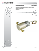
Instructions 95-8631 Volumetric Infrared Hydrocarbon Gas Process Monitor for Light Hydrocarbons PIRVOLLT 3.
Table Of Contents APPLICATION. . . . . . . . . . . . . . . . . . . . . . . . . . . . . . . . . . . . . . . . . . . . . 1 FEATURES. . . . . . . . . . . . . . . . . . . . . . . . . . . . . . . . . . . . . . . . . . . . . . . 1 SPECIFICATIONS. . . . . . . . . . . . . . . . . . . . . . . . . . . . . . . . . . . . . . . . . . 1 DESCRIPTION . . . . . . . . . . . . . . .
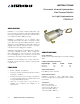
INSTRUCTIONS Volumetric Infrared Hydrocarbon Gas Process Monitor for Light Hydrocarbons PIRVOLLT APPLICATION PIRVOLLT is a point-type infrared hydrocarbon gas process monitor. It provides a continuous 4-20 milliampere (mA) output signal that is proportional to methane vapor concentrations from 0 to 100% by volume. PIRVOLLT is designed for use in extractive vapor sampling systems where the vapor concentration is likely to be above the lower flammability limit (LFL).
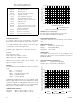
Table 1—Current Loop Output Levels and Corresponding Status Indications 0.6 mA 0.4 mA 0.2 mA 0.0 mA MAXIMUM LOOP RESISTANCE (OHMS) Current Level 23.0 mA 20.0 mA 4.0 mA 3.9-2.4 mA 2.2 mA 2.0 mA 1.8 mA 1.6 mA 1.0 mA 0.8 mA 900 Status Over 90% by volume 90% by volume Zero gas level (0% by volume) Negative zero drift Zero calibration in progress Span calibration in progress Calibration complete - remove gas Calibration fault Fouled optics 24 Vdc line low (less than 17.
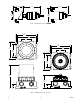
3.2 (78) 6.1 (154) 5.8 (147) 4.6 (116) 2.75 (70) B2029 Figure 3—PIRVOL Dimensions in Inches (mm) 5.86 (14.9) 5.2 (13.2) 2.7 (6.9) 5.86 (14.9) 5.2 (13.2) 4.7 (11.9) 2.7 (6.9) 3.46 (8.8) 4.7 (11.9) 3.46 (8.8) 6.57 (16.7) 3.77 (9.6) 1.28 (3.3) 1.28 (3.3) C2281 A2307 Figure 4—PIRTB Dimensions in Inches (cm) 3.
Operating Modes Certification— F M® Warmup ® When power is applied to the PIRVOLLT, it enters a Warmup mode (for approximately one minute) in which it performs diagnostic checks and allows the sensors to stabilize before beginning normal operation. The current output during this period is 0 mA. At the end of the warmup period with no faults present, the PIRVOLLT automatically enters the Normal operating mode. If a fault is present after the warmup, the current output will indicate a fault.
INSTALLATION The PIRVOLLT is designed to be threaded into a termination box, which is then mounted to a solid, vibration-free wall or post. The use of shielded cable in conduit or shielded armored cable is recommended for optimum RFI/EMI protection. In applications where the wiring cable is installed in conduit, the conduit must not be used for wiring to other electrical equipment. To assure proper operation, the resistance of the connecting wire must be within the specified limits.
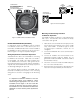
Figure 7—Short Cover PIRTB Figure 6—Tall Cover PIRTB with Window Wiring Procedure + – IMPORTANT Do not apply power until the wiring procedure is complete and has been verified. + 1. Locate the sensor where it will be accessible for maintenance. Excessive heat or vibration can result in premature failure of any electronic device and should be avoided if possible. PIRVOL CALIBRATE B2031 CALIBRATE SWITCH SHOWN INSTALLED, HOWEVER, FIELD CALIBRATION IS NOT REQUIRED UNDER NORMAL CIRCUMSTANCES.
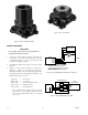
PIRTB TERMINATION BOX CALIBRATE SWITCH HOLD CALIBRATION MAGNET AT OUTSIDE BASE OF TERMINATION BOX AT THIS LOCATION TO ACTIVATE CALIBRATION SWITCH PIRVOL PROCESS MONITOR REMOTE LED CONTROL DEVICE, SUCH AS TRANSMITTER D2030 SUITABLE WIRING. MUST MEET ALL LOCAL CODES. Figure 11—Detector Separation Mounting and Connecting Procedure for Detector Separation C2056 The PIRTB should be mounted to a solid, vibration-free wall or post. The termination box should be electrically connected to earth ground.
STARTUP PROCEDURE TROUBLESHOOTING Refer to Table 2 to isolate and correct malfunctions with the PIRVOLLT. Note Caution should be exercised when applying this and any electronic device to explosive vapor ex traction and measurement applications. Typical hazards in these applications include small fitting vapor leaks, resulting in dangerous gas concentrations near or within the system enclosure. Any spark or arc may result in a fire or explosion in these conditions.
1. Disassembly and Cleaning Procedure The PIRVOLLT should be inspected periodically to ensure that its performance is not impaired by fouled optics or by clogging of the sample draw cup or hydrophobic filter. Inspection and/or periodic maintenance involves three different areas. Remove the sample draw cup from the front of the PIRVOLLT by pulling it straight off the electronics assembly (no tools needed). See Figure 12. 2.
ELECTRONICS ASSEMBLY SAMPLE DRAW CUP WINDOWS UL APPROVED O-RINGS MIRROR ASSEMBLY HYDROPHOBIC FILTER MIRRORS (2) C2032 Figure 12—PIRVOLLT Disassembly for Cleaning CALIBRATION Calibration Procedure In the event the PIRVOLLT optics are fouled and complete dis-assembly is required for cleaning, a zero calibration of the device may be required. This procedure ensures the signal output level is at 4 mA, and does not require application of span gas.
Table 3—Calibration Sequence Description Current LED Operator Action Normal operation/no gas present 4.0 mA Off Initiate calibration 2.2 mA On steady Initiate the calibration sequence by holding the calibration magnet against the side of the termination box or activating the external calibrate pushbutton for one second. Zero calibration complete 2.0 mA Flashing Re-apply magnet (or activate switch) for one second. Span calibration is not required.
ORDERING INFORMATION Stop plugs and reducers PIRVOLLT PROCESS GAS MONITOR Refer to the PIRVOLLT Model Matrix. replacement ir module Without cup, for field replacement only.
APPENDIX A CSA APPROVAL PIRVOLLT Process Gas Monitor CLASS 2258 02 - PROCESS CONTROL EQUIPMENT - For Hazardous Locations Class I, Div. 1, Groups B, C & D (T5); Class I, Div. 2, Groups A, B, C & D (T3C). PointWatch Termination Box Model PIRTB CLASS 4828 01 - SIGNAL APPLIANCES - Combustible Gas Detection Instruments - For Hazardous Locations Class I, Div. 1, Groups B, C & D (T6). Class I, Div. 2, Groups A, B, C & D (T6). 3.
APPENDIX B ATEX / CE Approval atex Certification PIRVOLLT Process Gas Monitor 0539 II 2 G Ex d IIB+H2 T4-T6 Gb DEMKO 09 ATEX 148373X T6 (Tamb = –55°C to +50°C) T5 (Tamb = –55°C to +60°C) T4 (Tamb = –55°C to +75°C) IP66. FM ® APPROVED EN Standards: EN 50270: 2006 EN 60079-0: 2009 EN 60079-1: 2007 EN 60529: 1991+A1: 2000. Read and understand instruction manual before operating.
APPENDIX C IECEx Approval PIRVOLLT Process Gas Monitor IECEx ULD 11.0007X Ex d IIB+H2 T4-T6 Gb T6 (Tamb = –55°C to +50°C) T5 (Tamb = –55°C to +60°C) T4 (Tamb = –55°C to +75°C) IP66. IEC Standards: IEC 60079-0: 2007 IEC 60079-1: 2007 IEC 60529, 2.1.ed.+Corr. 1:2003+2:2007. CONDITIONS OF CERTIFICATION: The Process Gas Monitor, Model PIRVOL, has a threaded wire feed through incorporating flying leads.
95-8631 Detector Electronics Corporation 6901 West 110th Street Minneapolis, MN 55438 USA X3301 Multispectrum IR Flame Detector PointWatch Eclipse® IR Combustible Gas Detector FlexVu® Universal Display w/ GT3000 Toxic Gas Detector Eagle Quantum Premier® Safety System T: 952.941.5665 or 800.765.3473 F: 952.829.8750 W: http://www.det-tronics.com E: det-tronics@det-tronics.