
Manual

2
3.1 95-8631
CURRENT OUTPUT—
4 to 20 mA current source (non-isolated). For output
levels below 4.0 mA and above 20 mA, refer to Table 1.
To convert PIRVOLLT current output to % by volume gas
concentration, use the following formula:
(milliamp signal – 4.0) x 6.25 = % by volume methane
Example:
(4.0 – 4.0) x 6.25 = 0%
(12.0 – 4.0) x 6.25 = 50% by volume
(20.0 – 4.0) x 6.25 = 100% by volume.
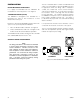
Maximum loop resistance: 580 ohms at +24 Vdc. See
Figure 1 for further information.
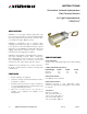
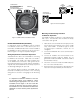
WIRING—
The PIRVOLLT has five 22 AWG wires, 20 inches (50 cm)
long.
Red = + 24 volts dc
Black = – (common)
White = 4 to 20 mA signal output
Yellow = Calibration input
Green = Chassis ground
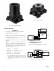
Field Wiring: 18 AWG minimum is recommended for field
wiring. Larger diameter wire may be required to maintain
a minimum of 18 Vdc (including ripple) at the sensor for all
operating conditions (see Figure 2). For maximum EMI/
RFI protection, shielded cable is recommended.
TEMPERATURE RANGE—
Operating: –40°F to +167°F (–40°C to +75°C).
Storage: –40°F to +185°F (–40°C to +85°C).
HUMIDITY (non-condensing)—
0 to 99% relative humidity (Det-Tronics verified)
5 to 95% relative humidity (CSA verified).
ENCLOSURE MATERIALS—
Copper-free aluminum (clear anodized) or 316 stainless
steel.
SAMPLE DRAW CUP—
Material: Aluminum or stainless steel.
Fittings: Nickel-plated Brass.
Tubing Size: 1/4 inch O.D.
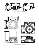
DIMENSIONS—
See Figure 3 for dimensions of the PIRVOLLT and
Figure 4 for dimensions of the PointWatch Termination
Box Model PIRTB.
SHIPPING WEIGHT (Approximate)—
Aluminum: 1.9 pounds (0.9 kilogram).
Stainless Steel: 5.0 pounds (2.3 kilograms).
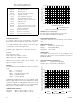
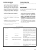
Table 1—Current Loop Output Levels
and Corresponding Status Indications
Figure 1—4 to 20 mA Current Loop Resistance
C1964
18
20 22 24
POWER SUPPLY VOLTAGE (VDC)
26 28 30 32
MAXIMUM LOOP RESISTANCE (OHMS)
400
500
600
700
800
900
LOOP RESISTANCE (OHMS)
Figure 2—PIRVOL Wiring Requirements
A2432
18 20 22 24
POWER SUPPLY VOLTAGE (VDC)
26 28 30 32
MAXIMUM DISTANCE FROM POWER SUPPLY TO PIRVOLLT IN FEET
16 AWG14 AWG12 AWG
18 AWG
500
1000
1500
2000
2500
0
Current Level Status
23.0 mA Over 90% by volume
20.0 mA 90% by volume
4.0 mA Zero gas level (0% by volume)
3.9-2.4 mA Negative zero drift
2.2 mA Zero calibration in progress
2.0 mA Span calibration in progress
1.8 mA Calibration complete - remove gas
1.6 mA Calibration fault
1.0 mA Fouled optics
0.8 mA 24 Vdc line low (less than 17.5 Vdc)
0.6 mA
Calibrate input active at power-up
(probable wiring fault)
0.4 mA Active channel fault
0.2 mA Reference channel fault
0.0 mA CPU system fault, warmup