Instructions Multispectrum IR Flame Detector X3301 19.
Table of Contents DESCRIPTION . . . . . . . . . . . . . . . . . . . . . . . . . . . . . 1 TROUBLESHOOTING . . . . . . . . . . . . . . . . . . . . . . 14 Outputs . . . . . . . . . . . . . . . . . . . . . . . . . . . . . . . . 1 LED . . . . . . . . . . . . . . . . . . . . . . . . . . . . . . . . . . . 2 MAINTENANCE . . . . . . . . . . . . . . . . . . . . . . . . . . . 15 oi (Optical Integrity) . . . . . . . . . . . . . . . . . . . . . . 2 Cleaning Procedure . . . . . . . . . . . . . . . . . . .
INSTRUCTIONS Multispectrum IR Flame Detector X3301 Important Be sure to read and understand the entire instruction manual before installing or operating the flame detection system. Any deviation from the recommendations in this manual may impair system performance and compromise safety. ATTENTION The X3301 includes the Automatic oi ® (Optical Integrity) feature — a calibrated performance test that is automatically performed once per minute to verify complete detector operation capabilities.
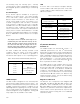
The Auxiliary relay has normally open / normally closed contacts, and is configurable for energized or de-energized operation, and latching or non-latching operation. LED A tri-color LED on the detector faceplate indicates normal condition and notifies personnel of fire alarm or fault conditions. Table 2 indicates the condition of the LED for each status. 0 to 20 mA Output A 0 to 20 mA output is available as an option (in addition to the three relays).
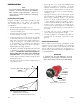
Integral Wiring Compartment CAUTION These tests require disabling of all extinguishing devices to avoid release resulting from a successful test. All external wiring to the device is connected within the integral junction box. The detector is furnished with four conduit entries, with either 3/4 inch NPT or M25 threads. The Mag oi test is performed by placing a magnet at the location marked "MAG OI" on the outside of the detector (see Figure 2).
General APPLICATION Information Important safety notes Warning Do not open the detector assembly in a hazardous area when power is applied. The detector contains limited serviceable components and should never be opened. Doing so could disturb critical optical alignment and calibration parameters, possibly causing serious damage.
INSTALLATION note The recommended lubricant for threads and O-rings is a silicone free grease (p/n 005003001) available from Det-Tronics. Under no circumstances should a lubricant containing silicone be used. • Dense fog, rain or ice can absorb IR radiation and reduce the sensitivity of the detector. To ensure optimum performance, be certain that the internal optical heater is enabled on detectors that are used in applications where snow, ice, and/condensation are likely to occur.
Protection Against Moisture Damage note R e f e r t o “ Po w e r C o n s u m p t i o n” i n t h e “Specifications” section of this manual. It is important to take proper precautions during installation to ensure that moisture will not come in contact with the electrical connections or components of the system. The integrity of the system regarding moisture protection must be maintained for proper operation and is the responsibility of the installer.
Relay and 0-20 mA Output Models EOL Resistors (Not Used with EQP Model) Follow the instructions below to install the X3301. 1. Make field connections following local ordinances and guidelines in this manual. To ensure that the insulating material of the wiring terminal block will not be affected by the heat generated by EOL resistors, observe the following guidelines when installing the resistors. –– Figure 4 shows the wiring terminal strip located inside the detector’s integral junction box. 1.
Figure 4—X3301 Terminal Block 9 mA + 19 mA – 29 SPARE 8 mA + REF 18 mA – REF 28 SPARE 7 COM FIRE 17 COM FIRE 27 COM AUX 6 N.O. FIRE 16 N.O. FIRE 26 N.O. AUX 5 N.C. FIRE 15 N.C. FIRE 25 N.C. AUX 4 COM FAULT 14 COM FAULT 24 RS-485 A 3 N.O. FAULT 13 N.O.
X3301 DETECTOR FIRE ALARM PANEL ALARM + 24 VDC – 9 mA + 19 mA – SPARE 29 8 mA + REF 18 mA – REF SPARE 28 7 COM FIRE2 COM FIRE 17 COM AUX 27 6 N.O. FIRE2 N.O. FIRE 16 N.O. AUX 26 N.C. AUX 25 5 N.C. FIRE2 4 E.O.L. DEVICE4 N.C. FIRE 15 COM FAULT1 COM FAULT 14 RS-485 A 24 3 N.O. FAULT1 N.O.
X3301 IR DETECTOR X3301 IR DETECTOR PLC PLC 9 600 Ω MAX AT 24 VDC 19 mA – mA + + 8 mA + REF – 7 COM FIRE mA + 24 VDC SPARE 28 + 8 mA + REF COM AUX 27 – 7 COM FIRE mA – REF 17 N.O. FIRE N.O. FIRE 16 N.O. AUX 26 5 N.C. FIRE N.C. FIRE 15 N.C. AUX 25 COM FAULT COM FAULT 14 RS-485 A 24 13 3 N.O. FAULT 2 24 VDC + 12 24 VDC – 11 N.O. FAULT mA + 24 VDC – 28 COM AUX 27 N.O. FIRE N.O. FIRE 16 N.O. AUX 26 5 N.C. FIRE N.C. FIRE 15 N.C.
5. Check all field wiring to be sure that the proper connections have been made. EQP Model 1. Connect external wires to the appropriate terminals inside the device junction box, shown in Figure 13. See Figure 14 for terminal identification. 6. Replace the device cover and apply input power. 7. 2. Connect the shield of the power cable to “earth ground” at the power source. 3. Connect shields for the LON cable as indicated.
19.
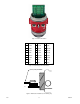
ADDRESS SWITCHES SENSOR MODULE REMOVED FROM HOUSING A2191 Figure 16—Location of Address Switches The address number is binary encoded with each switch having a specific binary value with switch 1 being the LSB (Least Significant Bit), see Figure 17. The device’s LON address is equal to the added value of all closed rocker switches. All “Open” switches are ignored. Setting Device Network Addresses (EQP Model Only) Overview of Network Addresses Each device on the LON must be assigned a unique address.
Table 3—Current Level Output Troubleshooting Guide STARTUP PROCEDURE When installation of the equipment is complete, perform the “Fire Alarm Test” below. Current Level (±0.3 mA) Status Action 0 mA Power Fault Check system wiring 1 mA General Fault Cycle power 1 2 mA oi Fault Fire Alarm Test 1. Disable any extinguishing connected to the system. equipment that is 2. Apply input power to the system. 3 mA 3.
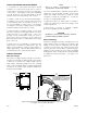
MAINTENANCE LOOSEN TWO CAPTIVE SCREWS IMPORTANT Pe r i o d i c fl a m e p a t h i n s p e c t i o n s a re n o t recommended, since the product is not intended to be serviced and provides proper ingress protection to eliminate potential deterioration of the flamepaths. GRASP VISOR AND REMOVE oi PLATE Warning The sensor module (“front” half of the detector) contains no user serviceable components and should never be opened.
FEATURES X3301 Reflector Plates X3301 models are supplied with either a black or a stainless steel reflector plate. These plates are not interchangeable. Order the replacement that matches the reflector plate on your X3301 Flame Detector. • Long detection range to carbonaceous fires • Unequaled false alarm rejection • Responds to a fire in the presence of modulated blackbody radiation (i.e.
SPECIFICATIONS CURRENT OUTPUT (Optional)— 0 to 20 milliampere (±0.3 mA) dc current, with a maximum loop resistance of 500 ohms from 18 to 19.9 Vdc and 600 ohms from 20 to 30 Vdc. OPERATING VOLTAGE— 24 Vdc nominal (18 Vdc minimum, 30 Vdc maximum). Maximum ripple is 2 volts peak-to-peak. LON Output— Digital communication, transformer isolated (78.5 kbps). POWER CONSUMPTION— Without heater: 4 watts at 24 Vdc nominal; 5.2 watts at 24 Vdc in alarm. 4.5 watts at 30 Vdc nominal; 6.
ENCLOSURE MATERIAL— Copper-free aluminum (painted) or Stainless Steel (316/ CF8M Cast). CERTIFICATION— FM ® APPROVED Vibration— Conformance per FM 3260: 2000, MIL-STD 810C (Curve AW), DNV Note 2.4 (Class B). VdS WIRING— Field wiring screw terminals are UL/CSA rated for up to 14 AWG wire, and are DIN/VDE rated for 2.5 mm2 wire. Screw terminal required torque range is 3.5–4.4 in.-lbs. (0.4-0.5 N·m).
Replacement parts ORDERING INFORMATION The detector is not designed to be repaired in the field. If a problem should develop, refer to the Troubleshooting section. If it is determined that the problem is caused by an electronic defect, the device must be returned to the factory for repair.
X3301 Model Matrix MODEL X3301 DESCRIPTION Multispectrum IR Flame Detector TYPE MATERIAL A Aluminum S Stainless Steel (316) TYPE THREAD TYPE 4M 4 Port, Metric M25 4N 4 Port, 3/4" NPT TYPE OUTPUTS 11 Relay 13 Relay and 4-20 mA 14 Eagle Quantum Premier (EQP) 15 Relay and Pulse 16 Addressable Module Only (Third Party Type)* 21 Relay-Automotive 22 EQP Automotive 23 HART, Relay and 4-20 mA TYPE APPROVALS*** B INMETRO (Brazil) R VNIIPO/VNIIFTRI (Russia) S SIL T SIL/FM/CSA/ATEX
APPENDIX A FM Approval and Performance Report THE FOLLOWING ITEMS, FUNCTIONS AND OPTIONS DESCRIBE THE FM APPROVAL: • Explosion-proof for Class I, Div. 1, Groups B, C and D (T4A) Hazardous (Classified) Locations per FM 3615. • Dust-ignition proof for Class II/III, Div. 1, Groups E, F and G (T4A) Hazardous (Classified) Locations per FM 3615. • Nonincendive for Class I, Div. 2, Groups A, B, C and D (T3C) Hazardous (Classified) Locations per FM 3611. • Nonincendive for Class II, Div.
FM Approval and Performance Report – Continued RESPONSE CHARACTERISTICS Very High Sensitivity Fuel n-Heptane n-Heptane** n-Heptane n-Heptane Isopropanol Diesel** Ethanol Methanol Methanol Methanol** Methane JP-5** JP-5** JP-5** Office Paper 0.5 lb. Corrugated Panel Size 1 x 1 foot 1 x 1 foot 1 x 1 foot 6 in. x 6 in. 6 in. x 6 in. 1 x 1 foot 1 x 1 foot 6 in. x 6 in. 1 x 1 foot 1 x 1 foot 30 inch plume 1 x 1 foot 2 x 2 feet 2 x 2 feet 19" x 19" x 8" 18" x 36" Distance feet (m) 210 (64)* 210 (64)* 100 (30.
FM Approval and Performance Report – Continued RESPONSE CHARACTERISTICS IN THE PRESENCE OF FALSE ALARM SOURCES Very High Sensitivity False Alarm Source Sunlight, direct, modulated, reflected Vibration Radio frequency interference Distance feet (m) Fire Source Distance feet (m) Average Response Time (seconds)*** — 6-inch propane 6 (1.8) < 10 N/A 3-inch propane 10.5 (3.2) < 10 1 (0.3) 3-inch propane 12 (3.7) < 10 Arc welding, #7014 40 (12.2) 1 x 1 foot n-Heptane 40 (12.
FM Approval and Performance Report – Continued T-Low Sensitivity Distance feet (m) Fire Source Distance feet (m) Average Response Time (seconds)*** Sunlight, direct, unmodulated, reflected* — 1 x 1 foot n-Heptane 35 (10.7) <6 Sunlight, direct, modulated, reflected* — 1 x 1 foot n-Heptane 15 (4.6) <4 Arc welding, steady, #7014 5 (1.5) 1 x 1 foot n-Heptane 50 (15.2) 10 Arc welding, modulated, #7014 5 (1.5) 1 x 1 foot n-Heptane 30 (9.1) 3 70 w sodium vapor, unmodulated 3 (0.
FM Approval and Performance Report – Continued FALSE ALARM IMMUNITY Very High Sensitivity False Alarm Source Sunlight, direct, reflected Vibration Radio frequency interference Arc welding 6 kw heater 250 w vapor lamp 300 w incandescent lamp 500 w unshielded quartz halogen lamp 500 w shielded quartz halogen lamp 1500 w electric radiant heater Two 34 w fluorescent lamps Distance feet (m) — N/A 1 (0.3) 40 (12.2) 3 (0.9) 3 (0.9) 3 (0.9) 8 (2.4) 8 (2.4) 3 (0.9) 3 (0.
FM Approval and Performance Report – Continued FIELD of view Very High Sensitivity Fuel Size Distance feet (m) Horizontal (degrees) Avg. Horiz. Response Time (seconds)*** Vertical (degrees) Avg. Vert. Response Time (seconds)*** n-Heptane 1 x 1 foot 150* (45.7) +45 -45 12 14 +45 -30 13 5 n-Heptane 1 x 1 foot 100 (30.5) +45 -45 6 3 +45 -30 3 2 n-Heptane 6 in. x 6 in. 80 (24.4) +45 -45 5 6 +45 -30 4 4 Isopropanol 6 in. x 6 in. 70 (21.
FM Approval and Performance Report – Continued Medium Sensitivity Fuel Size Distance feet (m) Horizontal (degrees) Avg. Horiz. Response Time (seconds)*** Vertical (degrees) Avg. Vert. Response Time (seconds)*** n-Heptane 1 x 1 foot 75 (22.9) +45 -45 9 6 +45 -30 10 7 n-Heptane 1 x 1 foot 50 (15.2) +45 -45 4 3 +45 -30 3 3 Diesel** 1 x 1 foot 60 (18.3) +45 -45 4 4 +45 -30 4 2 Ethanol 1 x 1 foot 60 (18.2) +45 -45 12 9 +45 -30 12 9 Methanol 1 x 1 foot 50 (15.
FM Approval and Performance Report – Continued HIGH RESOLUTION FIELD OF VIEW 15° 30° 0° 210 (64) 30° 180 (54.9) 45° 0° 15° 70 (21.3) 15° 30° 45° 150 (45.7) 30° 60 (18.3) 45° 45° 50 (15.2) 120 (36.5) 40 (12.2) 90 (27.4) 30 (9.1) 60 (18.3) 20 (6.1) 30 (9.1) 10 (3) 30 (9.1) 15° 10 (3) 30° 60 (18.3) 30° 20 (6.1) 90 (27.4) 30 (9.1) 15° 120 (36.5) 150 (45.7) 50 (15.2) 0° 180 (54.9) 15° 210 (64) 45° 30° 30° 70 (21.3) 45° 30° 30° 60 (18.
FM Approval and Performance Report – Continued 15° 30° 0° 210 (64) 15° 45° 30° 30° 180 (54.9) 45° 45° 150 (45.7) 120 (36.5) 90 (27.4) 60 (18.3) 30 (9.1) 90 (27.4) 30° 15° 120 (36.5) 45° 150 (45.7) 0° 180 (54.9) DETECTOR VERTICAL FIELD OF VIEW WITH DETECTOR AT 45° FROM HORIZONTAL. 15° 30° Field of View at Indicated Distance in Feet (m) for Ethanol at Very High Sensitivity (1 x 1 foot) 30° 0° 15° 40 (12.2) 10 (3) 20 (6.1) 30 (9.1) 40 (12.2) 50 (15.2) 60 (18.3) 70 (21.3) 80 (24.
FM Approval and Performance Report – Continued 30° 45° 0° 15° 100 (30.5) 15° 90 (27.4) 80 (24.4) 70 (21.3) 60 (18.3) 50 (15.2) 40 (12.2) 30 (9.1) 20 (6.1) 10 (3) 30° 30° 45° 45° 30° 45° 60 (18.3) 30° 45° 50 (15.2) 30 (9.1) 20 (6.1) 10 (3) Field of View at Indicated Distance in Feet (m) for Methanol at Medium Sensitivity (1 x 1 foot) 15° 30° 60 (18.3) 15° 40 (12.2) Field of View at Indicated Distance in Feet (m) for n-Heptane at Medium Sensitivity (1 x 1 foot) 0° 15° 70 (21.
APPENDIX B CSA Approval Multispectrum IR Flame Detector/Controller X3301 Series, rated 18-30 Vdc, 4.6 Watts to 17 Watts. Relay contacts rated 30 Vdc, 5 Amps. Note Hazardous location testing has been successfully completed on the Model X3301 series from an ambient temperature range of –55°C to +125°C; however, the detector label marking indicates –40°C to +75°C.
APPENDIX C ATEX / CE Approval EC-TYPE EXAMINATION CERTIFICATE DEMKO 01 ATEX 130204X Increased Safety Model FM APPROVED II 2 G 0539 II 2 D Ex d e IIC T6–T5 Gb Ex tb IIIC T130°C T6 (Tamb = –50°C to +60°C) T5 (Tamb = –50°C to +75°C) IP66/IP67. ® Flameproof Model FM APPROVED II 2 G II 2 D Ex d IIC T6–T4 Gb Ex tb IIIC T130°C T6 (Tamb = –55°C to +60°C) T5 (Tamb = –55°C to +75°C) T4 (Tamb = –55°C to +125°C) IP66/IP67.
NOTE Operational performance verified from –40°C to +75°C. Note An optional third party addressable module can only be used within the Ex d flameproof model unless the addressable module is component certified as Ex e for use within the Ex d e increased safety model. NOTE Refer to “EOL Resistors” section for installation details.
APPENDIX D IECEx Approval IECEx Certificate of Conformity DEMKO IECEx ULD 06.0017X Ex d e IIC T6-T5 Gb Ex d IIC T6-T4 Gb Ex tb IIIC T130°C Ex tb IIIC T130°C T6 (Tamb = –50°C to +60°C) or T6 (Tamb = –55°C to +60°C) T5 (Tamb = –50°C to +75°C) T5 (Tamb = –55°C to +75°C) IP66/IP67. T4 (Tamb = –55°C to +125°C) IP66/IP67. Compliance with: IEC 60079-0: 2007, ed. 5 IEC 60079-1: 2007, ed. 6 IEC 60079-7: 2006, ed. 4 IEC 60079-31: 2008, ed. 1 EN/IEC 60529: 2001.
APPENDIX E EN54 Approvals Conventional Output AGENCY VdS – Constructive Product Directive Certificate/Approval Number Basis of Approval Certificate/Approval Number Basis of Approval 0786 – CPD – 20453 EN 54-10 + A1 — — G 202136 VdS 2344 VdS 2504 EN 54-10 + A1 G 212019 VdS 2344 VdS 2504 EN 54-10 + A1 EN 54-17 S 212002* VdS 2344 EN 54-13 S 212002* VdS 2344 EN 54-13 — — 0832 – CPD – 1381 EN 54-10 + A1 EN 54-17 973e/03 EN 54-10 + A1 973a/03 EN 54-10 + A1 EN 54-17 VdS BRE – Constructiv
APPENDIX F Offshore Approvals USCG APPROVAL Coast Guard Approval No. 161.002/49/0 The scope of this approval is for a fire detection system meeting 46 CFR 161.002, as part of the Eagle Quantum Premier System. MARINE EQUIPMENT DIRECTIVE DNV Certificate No. MED-B-5872. Is found to comply with the requirements in the following Regulations / Standards: Annex A.1, item No. A.1/3.51 and Annex B, Module B in the Directive. SOLAS 74 as amended, Regulation II-2/7 & X/3, 2000 HSC Code 7, FSS Code 9 and IMO MSC.
APPENDIX G Additional Approvals SIL 2 IEC 61508 Certified SIL 2 Capable. Applies to specific models – refer to the SIL 2 Certified X3301 Safety manual (95-8582) for details. FRANCE NF-SSI AFNOR Identification No: LIR 007 A0. www.marque-nf.com RUSSIA VNIIFTRI CERTIFICATE OF CONFORMITY to TP TC 012/2011 2ExdeIICT6/T5 IP66 T6 (Tamb = –50°C to +60°C) T5 (Tamb = –50°C to +75°C). – or – 1ExdIICT6/T5/T4 IP66 T6 (Tamb = –55°C to +60°C) T5 (Tamb = –55°C to +75°C) T4 (Tamb = –55°C to +125°C).
95-8527 FlexSonicTM Acoustic Leak Detector X3301 Multispectrum X3301 Multispectrum IR Flame Detector PointWatch Eclipse® PointWatch Eclipse ® IR Combustible Gas Detector FlexVu® Universal Display Phone: 952.946.6491 Corporate IR FlameOffice Detector IR Combustible Gas Detector w/ GT3000 Toxic Gas Detector Toll-free: 800.765.3473 6901 West 110th Street Fax: 952.829.8750 Minneapolis, MN 55438 USA det-tronics@det-tronics.com www.det-tronics.