Instructions 95-8554 IR Flame Detector X9800 11.
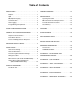
Table of Contents Description . . . . . . . . . . . . . . . . . . . . . . . . . . . . . 1 Troubleshooting . . . . . . . . . . . . . . . . . . . . . . . 14 Outputs . . . . . . . . . . . . . . . . . . . . . . . . . . . . . . . . 1 LED . . . . . . . . . . . . . . . . . . . . . . . . . . . . . . . . . . . 2 oi (Optical Integrity) . . . . . . . . . . . . . . . . . . . . . .
INSTRUCTIONS IR Flame Detector X9800 Important Be sure to read and understand the entire instruction manual before installing or operating the flame detection system. Any deviation from the recommendations in this manual may impair system performance and compromise safety. ATTENTION The X9800 includes the Automatic oi ® (Optical Integrity) feature — a calibrated performance test that is automatically performed once per minute to verify complete detector operation capabilities.
The Auxiliary relay has normally open / normally closed contacts, and is configurable for energized or de-energized operation, and latching or non-latching operation. LED A tri-color LED on the detector faceplate indicates normal condition and notifies personnel of fire alarm or fault conditions. Table 2 indicates the condition of the LED for each status. 0 to 20 mA Output A 0 to 20 mA output is available as an option (in addition to the three relays).
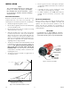
Integral Wiring Compartment CAUTION These tests require disabling of all extinguishing devices to avoid release resulting from a successful test. All external wiring to the device is connected within the integral junction box. The detector is furnished with four conduit entries, with either 3/4 inch NPT or M25 threads. The Mag oi test is performed by placing a magnet at the location marked "MAG OI" on the outside of the detector (see Figure 2).
General Application Information EMI/RFI Interference The X9800 is resistant to interference by EMI and RFI, and is EMC Directive compliant and CE marked. It will not respond to a 5 watt walkie-talkie at distances greater than 1 foot (0.3 m). Response Characteristics Response is dependent on the detector's sensitivity setting, distance, type of fuel, temperature of the fuel, and time required for the fire to come to equilibrium.
Important Safety Notes Factors Inhibiting Detector Response Windows Warning Do not open the detector assembly in a hazardous area when power is applied. The detector contains limited serviceable components and should never be opened. Doing so could disturb critical optical alignment and calibration parameters, possibly causing serious damage. Glass and Plexiglas windows significantly attenuate radiation and must not be located between the detector and a potential flame source.
Installation note The recommended lubricant for threads and O‑rings is a silicone free grease (p/n 005003001) available from Detector Electronics. Under no circumstances should a lubricant containing silicone be used. • Dense fog, rain as well as certain gases and vapors can absorb IR radiation and reduce the sensitivity of the detector. • If possible, fire tests can be conducted to verify correct detector positioning and coverage.
Protection Against Moisture Damage note R e f e r t o “ Po w e r C o n s u m p t i o n” i n t h e “Specifications” section of this manual. It is important to take proper precautions during installation to ensure that moisture will not come in contact with the electrical connections or components of the system. The integrity of the system regarding moisture protection must be maintained for proper operation and is the responsibility of the installer.
Relay and 0-20 mA Output Models EOL Resistors (Not Used with EQP Model) Follow the instructions below to install the X9800. To ensure that the insulating material of the wiring terminal block will not be affected by the heat generated by EOL resistors, observe the following guidelines when installing the resistors. 1. Make field connections following local ordinances and guidelines in this manual. Refer to Figures 4 through 12. 2.
X9800 DETECTOR FIRE ALARM PANEL ALARM + 24 VDC – 19 4-20 mA – SPARE 29 18 4-20 mA – REF SPARE 28 COM AUX 27 N.O. AUX 26 N.C. AUX 25 9 4-20 mA + 8 4-20 mA + REF 7 COM FIRE2 COM FIRE 17 6 N.O. FIRE2 N.O. FIRE 16 5 N.C. FIRE2 4 E.O.L. DEVICE4 N.C. FIRE 15 COM FAULT1 COM FAULT 14 RS-485 A 24 3 N.O. FAULT1 N.O.
X9800 DETECTOR X9800 DETECTOR PLC PLC 600 Ω MAX AT 24 VDC 9 4-20 mA + 19 4-20 mA – 29 + 8 4-20 mA + REF 18 28 + – 7 17 27 – 4 TO 20 mA 24 VDC 600 Ω MAX AT 24 VDC 9 + 6 16 26 5 15 25 4 TO 20 mA 24 VDC 13 3 2 24 14 4 – 24 VDC + 12 24 VDC – 11 MAN Oi – 28 17 27 6 16 26 5 15 25 4 14 24 2 24 VDC + 12 1 24 VDC – 11 23 13 MAN Oi 22 C2179 24 VDC – 21 24 VDC – 21 Oi TEST1 24 VDC + – Figure 10—X9800 Detector Wired for Non-Isolated 0 to 20 mA Curren
5. Check all field wiring to be sure that the proper connections have been made. EQP Model 1. Connect external wires to the appropriate terminals inside the device junction box, shown in Figure 13. See Figure 14 for terminal identification. 6. Replace the device cover and apply input power. 2. Connect the shield of the power cable to “earth ground” at the power source. 7. Make the final sighting adjustments and use a 14 mm hex wrench to ensure that the mounting arm assembly is tight. 3.
11.
ADDRESS SWITCHES SENSOR MODULE REMOVED FROM HOUSING A2191 Figure 16—Location of Address Switches The address number is binary encoded with each switch having a specific binary value with switch 1 being the LSB (Least Significant Bit), see Figure 17. The device’s LON address is equal to the added value of all closed rocker switches. All “Open” switches are ignored.
Startup Procedure Table 3—Current Level Output Troubleshooting Guide When installation of the equipment is complete, perform the “Fire Alarm Test” below. Fire Alarm Test 1. Disable any extinguishing connected to the system. equipment that is 2. Apply input power to the system. 3. Initiate an oi test. (See “Magnetic oi / Manual oi” under Optical Integrity in the Description section of this manual. Current Level (±0.3 mA) Status Action 0 mA Power Fault Check system wiring.
NOTE Refer to the X9800 Safety manual (95-8672) for specific requirements and recommendations applicable to the proper installation, operation, and maintenance of all SIL-Certified X9800 Flame Detectors. LOOSEN TWO CAPTIVE SCREWS To maintain maximum sensitivity and false alarm resistance, the viewing windows of the X9800 must be kept relatively clean. Refer to the following procedure for cleaning instructions.
Features Specifications • Responds to a fire in the presence of modulated blackbody radiation (i.e. heaters, ovens, turbines) without false alarm. OPERATING VOLTAGE— 24 Vdc nominal (18 Vdc minimum, 30 Vdc maximum). Maximum ripple is 2 volts peak-to-peak. • High speed capability — 30 milliseconds. • Built-in data logging / event monitoring, up to 1500 events (up to 1000 general, 500 alarms). • Microprocessor controlled heated optics increased resistance to moisture and ice.
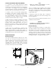
WIRING— Field wiring screw terminals are UL/CSA rated for up to 14 AWG wire, and are DIN/VDE rated for 2.5 mm2 wire. Screw terminal required torque range is 3.5–4.4 in.-lbs. (0.4-0.5 N·m). 100% REPRESENTS THE MAXIMUM DETECTION DISTANCE FOR A GIVEN FIRE. THE SENSITIVITY INCREASES AS THE ANGLE OF INCIDENCE DECREASES. VIEWING ANGLE 15° 30° 0° 100 ft (30.5 m) 15° Important: 18 Vdc minimum must be available at the detector.
Replacement Parts Ordering Information The detector is not designed to be repaired in the field. If a problem should develop, refer to the Troubleshooting section. If it is determined that the problem is caused by an electronic defect, the device must be returned to the factory for repair.
X9800 Model Matrix MODEL DESCRIPTION X9800 Single Frequency IR Flame Detector TYPE MATERIAL A Aluminum S Stainless Steel (316) TYPE THREAD TYPE 4M 4 PORT, METRIC M25 4N 4 PORT, 3/4" NPT TYPE OUTPUTS 11 Relay 13 Relay and 4-20 mA 14 Eagle Quantum Premier (EQP) 15 Relay and Pulse 16 Addressable Module Only (Third Party Type)* 23 HART, Relay and 4-20 mA TYPE APPROVALS** R VNIIPO/VNIIFTRI (Russia) T SIL/FM/CSA/ATEX/CE/IECEx W FM/CSA/ATEX/CE/IECEx TYPE CLASSIFICATION 1 Division/
APPENDIX A FM Approval and Performance Report THE FOLLOWING ITEMS, FUNCTIONS AND OPTIONS DESCRIBE THE FM APPROVAL: • Explosion-proof for Class I, Div. 1, Groups B, C and D (T5) Hazardous (Classified) Locations per FM 3615. • Dust-ignition proof for Class II/III, Div. 1, Groups E, F and G (T5) Hazardous (Classified) Locations per FM 3615. • Nonincendive for Class I, Div. 2, Groups A, B, C and D (T3) Hazardous (Classified) Locations per FM 3611. • Nonincendive for Class II, Div.
FM Approval and Performance Report – Continued RESPONSE CHARACTERISTICS Very High Sensitivity Fuel Size / Flow Rate Distance feet (m) Typical Response Time (seconds)* TDSA Quick Fire n-Heptane 1 x 1 foot 85 (25.9) 15 On Off Methane 32 inch plume 60 (18.3) 5 On Off Propane Torch 2 (0.6) 0.04 On On *Add 2 seconds for EQP model. High Sensitivity Fuel Size / Flow Rate Distance feet (m) Typical Response Time (seconds)* TDSA Quick Fire n-Heptane 1 x 1 foot 50 (15.
FM Approval and Performance Report – Continued FALSE ALARM IMMUNITY High Sensitivity, TDSA On, Quick Fire Off False Alarm Souce Distance feet (m) Modulated Response Unmodulated Response — No alarm No alarm Sunlight, direct, reflected NA No alarm No alarm Arc welding 15 (4.6) No alarm No alarm 70 w sodium vapor lamp 3 (0.9) No alarm No alarm 250 w mercury vapor lamp 3 (0.9) No alarm No alarm 300 w incandescent lamp 3 (0.
APPENDIX B CSA Approval PRODUCTS CLASS 4818 04 - SIGNAL APPLIANCES - Systems - For Hazardous Locations Class I, Division 1, Groups B, C, and D (T5); Class II, Division 1, Groups E, F, and G (T5); Class I, Division 2, Groups A, B, C, and D (T3); Class II, Division 2, Groups F and G (T3); Class III; Enclosure NEMA/Type 4X; Infrared Flame Detector/Controller X9800 series, rated 18-30 Vdc, 2.1 Watts to 16.5 Watts. Relay contacts rated 5 Amps @ 30 Vdc. APPLICABLE REQUIREMENTS CSA Std C22.2 No.
APPENDIX C ATEX / CE Approval EC-TYPE EXAMINATION CERTIFICATE DEMKO 02 ATEX 132195X Increased Safety Model FM APPROVED II 2 G II 2 D Ex d e IIC T6–T5 Gb Ex tb IIIC T80°C T6 (Tamb = –50°C to +60°C) T5 (Tamb = –50°C to +75°C) IP66/IP67. 0539 ® Flameproof Model FM APPROVED II 2 G II 2 D Ex d IIC T6–T5 Gb Ex tb IIIC T80°C T6 (Tamb = –55°C to +60°C) T5 (Tamb = –55°C to +75°C) IP66/IP67. 0539 ® Compliance with: EN 60079-0: 2009 EN 60079-1: 2007 EN 60079-7: 2007 EN 60079-31: 2009 EN / IEC 60529: 2001.
NOTE Operational performance verified from –40°C to +75°C. note An optional third party addressable module can only be used within the Ex d flameproof model unless the addressable module is component certified as Ex e for use within the Ex d e increased safety model. NOTE Refer to “EOL Resistors” section for installation details.
APPENDIX D IECEx Approval IECEx Certificate of Conformity DEMKO IECEx ULD 06.0018X Ex d e IIC T6-T5 Gb Ex d IIC T6-T5 Gb Ex tb IIIC T80°C Ex tb IIIC T80°C T6 (Tamb = –50°C to +60°C) or T6 (Tamb = –55°C to +60°C) T5 (Tamb = –50°C to +75°C) T5 (Tamb = –55°C to +75°C) IP66/IP67. IP66/IP67. Compliance with: IEC 60079-0: 2007, Ed. 5 IEC 60079-1: 2007, Ed. 6 IEC 60079-7: 2006, Ed. 4 IEC 60079-31: 2008, Ed. 1 EN / IEC 60529: 2001.
APPENDIX E EN54 ApprovalS Conventional Output AGENCY VdS – Construction Product Directive Certificate/Approval Number Basis of Approval Basis of Approval 0786 – CPD – 20779 EN 54-10 + A1 — — G 203084 VdS 2344 VdS 2504 EN 54-10 + A1 — — S 212002* VdS 2344 EN 54-13 S 212002* VdS 2344 EN 54-13 — — 0832 – CPD – 1377 EN 54-10 + A1 EN 54-17 973e/01 EN 54-10 + A1 973a/01 EN 54-10 + A1 EN 54-17 VdS BRE – EC – Certificate of Conformity LPCB LON Output Certificate/Approval Number * Approve
APPENDIX F ADDITIONAL APPROVALS SIL 2 IEC 61508 Certified SIL 2 Capable. Applies to specific models – refer to the SIL 2 Certified X9800 Safety Manual (95-8672) for details. RUSSIA VNIIFTRI CERTIFICATE OF CONFORMITY GOST R 51330.X-99 2ExdeIICT6/T5 IP66 T6 (Tamb = –55°C to +60°C) T5 (Tamb = –55°C to +75°C). – OR – 1ExdIICT6/T5 IP66 T6 (Tamb = –55°C to +60°C) T5 (Tamb = –55°C to +75°C) VNIIPO CERTIFICATE OF CONFORMITY TO TECHNICAL REGULATIONS, GOST R 53325-2009 11.
95-8554 Detector Electronics Corporation 6901 West 110th Street Minneapolis, MN 55438 USA X3301 Multispectrum IR Flame Detector PointWatch Eclipse® IR Combustible Gas Detector FlexVu® Universal Display w/ GT3000 Toxic Gas Detector Eagle Quantum Premier® Safety System T: 952.941.5665 or 800.765.3473 F: 952.829.8750 W: http://www.det-tronics.com E: det-tronics@det-tronics.