
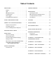
Specifications


95-8554811. 1
Relay and 0-20 mA Output Models
Follow the instructions below to install the X9800.
1. Make field connections following local ordinances
and guidelines in this manual. Refer to Figures 4
through 12.
2. Check all field wiring to be sure that the proper
connections have been made.
IMPORTANT
Do not test any wiring connected to the detector
with a meg-ohmmeter. Disconnect wiring at
the detector before checking system wiring for
continuity.
3. Make the final sighting adjustments and use a 14 mm
hex wrench to ensure that the mounting arm assembly
is tight.
EOL RESISTORS (Not Used with EQP Model)
To ensure that the insulating material of the wiring
terminal block will not be affected by the heat generated
by EOL resistors, observe the following guidelines when
installing the resistors.
1. Required EOL resistor power rating must be 5 watts
minimum.
NOTE
EOL resistors must be ceramic, wirewound
type, rated 5 watts minimum, with actual power
dissipation not to exceed 2.5 watts.
This applies
to ATEX/IEC installations only.
2. Resistor leads should be cut to a length of
approximately 1 1/2 inches (40 mm).
3. Bend the leads and install the EOL resistor as shown
in Figure 6.
4. Maintain a 3/8 inch (10 mm) minimum gap between
the resistor body and the terminal block or any other
neighboring parts.
NOTE
The EOL resistor can only be used within the
ameproof terminal compartment. Unused conduit
entries shall be closed with suitable blanking
elements.
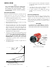
Figure 4—X9800 Terminal Block
Figure 6—EOL Resistor Installation
3/8 INCH (10 MM) GAP MINIMUM
1112
13
141516171819
B2126
BULKHEAD
9
8
7
6
5
4
3
2
1
19
18
17
16
15
14
13
12
11
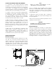
4-20 mA +
4-20 mA –
4-20 mA + REF
4-20 mA – REF
COM FIRE
COM FIRE
N.O. FIRE
N.O. FIRE
N.C. FIRE
N.C. FIRE
COM FAULT
COM FAULT
N.O. FAULT
N.O. FAULT
24 VDC +
24 VDC +
24 VDC –
24 VDC –
24 VDC –
29
28
27
26
25
24
23
22
21
SPARE
SPARE
COM AUX
N.O. AUX
N.C. AUX
RS-485 A
RS-485 B
MAN O
i
C2061
Figure 5—Wiring Terminal Identication