
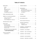
Specifications


95-8554611. 1
installation
NOTE
The recommended lubricant for threads and
O-rings is a silicone free grease (p/n 005003-
001) available from Detector Electronics. Under
no circumstances should a lubricant containing
silicone be used.
DETECTOR POSITIONING
Detectors should be positioned to provide the best
unobstructed view of the area to be protected. The
following factors should also be taken into consideration:
• Identify all high risk fire ignition sources.
• Be sure that enough detectors are used to adequately
cover the hazardous area.
• Be sure that the unit is easily accessible for cleaning
and other periodic servicing.
• Verify that all detectors in the system are properly
located and positioned so that any fire hazards are
within both the Field of View (FOV) and detection
range of the detector. Det-Tronics' Q1201C Laser
Aimer is recommended for establishing the detector's
FOV. Refer to Appendix A for specific information
regarding detector range and FOV.
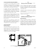
• The detector should be aimed downward at least 10
to 20 degrees to allow lens openings to drain (see
Figure 1). The detector should be positioned so
that its FOV does not cover areas outside the
hazardous area. This will minimize the possibility
of false alarms caused by activities outside the area
requiring protection.
• The detector must be mounted on a rigid surface in
a low vibration area.
• Dense fog, rain as well as certain gases and vapors
can absorb IR radiation and reduce the sensitivity of
the detector.
• If possible, fire tests can be conducted to verify
correct detector positioning and coverage.
• For ATEX installations, the X9800 Flame Detector
housing must be electrically connected to earth
ground.
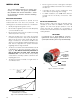
DETECTOR ORIENTATION
Refer to Figure 2 and ensure that the o
i
plate will be
oriented as shown when the X9800 is mounted and
sighted. This will ensure proper operation of the o
i
system and will also minimize the accumulation of
moisture and contaminants between the o
i
plate and the
viewing windows.
IMPORTANT
If removed, the
o
i
plate must be securely
tightened to ensure proper operation of the
o
i
system (40 oz./inches [28.2 N
.
cm] recommended).
Figure 1—Detector Orientation Relative to Horizon
IR VIEWING WINDOW
o
i
PLATE
PLACE MAGNET
HERE TO INITIATE
MAGNETIC o
i
o
i
MAGNET
DETECTOR
STATUS INDICATOR
B2174
Figure 2—Front View of the X9800
CENTER AXIS
OF DETECTOR
FIELD OF VIEW
CENTER AXIS
OF DETECTOR
FIELD OF VIEW
INCORRECT
CORRECT
NOTE: DETECTOR MUST ALWAYS BE AIMED
DOWNWARD AT LEAST 10 TO 20 DEGREES.
D1974