
Specifications


7 95-855411. 1
PROTECTION AGAINST MOISTURE DAMAGE
It is important to take proper precautions during
installation to ensure that moisture will not come in
contact with the electrical connections or components
of the system. The integrity of the system regarding
moisture protection must be maintained for proper
operation and is the responsibility of the installer.
If conduit is used, we recommend installing drains,
according to local codes, at water collection points
to automatically drain accumulated moisture. It is
also recommended to install at least one breather,
according to local codes, at upper locations to provide
ventilation and allow water vapor to escape.
Conduit raceways should be inclined so that water
will flow to low points for drainage and will not collect
inside enclosures or on conduit seals. If this is not
possible, install conduit drains above the seals to
prevent the collection of water or install a drain loop
below the detector with a conduit drain at the lowest
point of the loop.
Conduit seals are not required for compliance with
explosion-proof installation requirements, but are
highly recommended to prevent water ingress in
outdoor applications. Units with M25 threads must use
an IP66/IP67 washer to prevent water ingress.
WIRING PROCEDURE
Wire Size and Type
The system should be wired according to local codes.
The wire size selected should be based on the
number of detectors connected, the supply voltage
and the cable length. Typically 16 AWG or 2.5
mm
2
shielded cable is recommended. Wires should be
stripped 3/8 inch (9 mm). A minimum input voltage
of 18 Vdc must be present at the X9800.
NOTE
Refer to “Power Consumption” in the
“Specications” section of this manual.
The use of shielded cable is required to protect against
interference caused by EMI and RFI. When using cables
with shields, terminate the shields as shown in Figures
7 through 12, and Figure 15. Consult the factory if not
using shielded cable.
In applications where the wiring cable is installed in
conduit, the conduit must not be used for wiring to other
electrical equipment.
If disconnection of power is required, separate disconnect
capability must be provided.
CAUTION
Installation of the detector and wiring should be
performed only by qualied personnel.
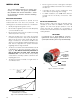
Detector Mounting
Install the mounting arm assembly on a rigid surface.
The ideal installation surface should be free of vibration
and suitable to receive 3/8 inch (M9) bolts with a length
of at least 1 inch (25 mm). The surface must also have
sufficient capacity to hold the detector and mounting
arm weights (See "Specifications" section). Refer to the
Q9033 Mounting Arm manual (95-8686) for additional
mounting information. See Figure 3 for dimensions.
13.1
(33.4)
10.6
(27.0)
4.0
(10.2)
4.0
(10.2)
3.0
(7.6)
3.0
(7.6)
4X ø0.42
(1.1)
E2069
NOTE: THIS ILLUSTRATION SHOWS THE
DETECTOR MOUNTED AT THE 10° MINIMUM.
THESE DIMENSIONS WILL CHANGE BASED
ON THE DETECTOR’S MOUNTING ANGLE.
Figure 3—Q9033 Mounting Arm without Collar Attachment Dimensions in Inches (cm)
(See Figure 1 for Correct Detector Orientation.)