
Installation Guide


En.12 DK2 Avalanche man.
ENGLISH
SNOWPLOW ASSEMBLY
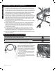
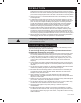
16. Assemble the blade angle locking handle with knob to the A frame so that it
operates the spring-loaded angle lock pin in the bracket on top of the A frame
smoothly. Bolt the end of the handle opposite the knob (16, g.16) to the eye in
the small tab in the A frame’s centre cross piece (6t, g.16) with an M8 x 25 mm
gr.8 bolt (48, g.16) and 2 x 8 mm washers. Secure with an 8 mm Nylock nut.
Bolt the handle to the hole in the angle lock pin with an M8 x 35 mm gr.8 bolt
(49, g.16) and 2 x 8 mm washers. Secure with an 8 mm Nylock nut.
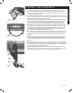
17. Attach the snow deector to the top ange of the plow. Place the deector
rubber along the top angle of the plow blade. On top of that place the short and
long metal deector battens.Bolt them into place with 7 M10 x 25 mm carriage
bolts down through all but the two end holes. In the end two holes, insert the
threaded ends of the two snowplow marker wands. Secure all with 9 x M10
Nylock nuts threaded on from below the ange.
18. Using two bolts and nuts, attach the light bar with the two lights to the top edge
of the winch support tower.
19. Connect the safety chain to the bottom of the winch mounting plate with the
threaded quick link. During transportation with the plow blade raised, the
clip hook should fasten to the hole in the angled tab just behind the strap
attachment point in the apex of the A frame, preventing the plow blade from
falling should anything fail.
20. It is normal for the whole assembly to rock back and forth when mounted,
with the plow blade moving side to side from 20 to 25 cm (8 to 10 in.) This
compensates for dierences in terrain between the surface the plow rides on
and what the vehicle is riding on. This exibility should not be reduced.
21. Insert the t-frame (PART 62) into the main frame and secure the tabs using the
safety clips (PART 61).
ELECTRICAL INSTALLATION
CAUTION! Before working on the winch or the wiring in your vehicle,
disconnect the battery and any other power sources.
CAUTION! For work connected with the vehicle, avoid touching any hot
surfaces such as the engine, radiator, hoses and exhaust pipes.
WINCH LEADS
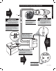
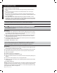
1. Connect the winch leads, tagged “To
Motor”, to the contacts on the winch motor as
shown. [winch leads photo] Be sure the rubber
caps cover the connections well to prevent
water entry. The red lead should be connected
to the positive (+ upper) terminal on the winch,
and the black lead connected to the negative
(- lower) winch terminal.
2. Lay the red and black leads down along
the winch support tower, using nylon ties to
secure them in place.
3. Use a nylon tie to retain the short cable
leash on the blue 2” connector plug cap to the
winch support tower.
C
A
U
TI
O
N! Be
f
ore working on the winch or the wiring in
y
our vehicle,
d
isconnect the batter
y
and an
y
other power sources.
C
A
U
TI
O
N! For work connected with the vehicle, avoid touching an
y
ho
t
s
ur
f
aces such as the engine, radiator, hoses and exhaust pipes.