Detcon Model 10/12 Control Card Test Fixture Operators Instruction Manual October 1, 2007 * Document 3385 * Revision 1.0 DETCON, Inc. 3200 Research Forest Dr., Building A-1 The Woodlands, Texas 77387 Ph. 713-559-9200 / Fax 281-298-2868 www.detcon.
Model 10/12 Control Card Test Fixture Table of Contents 1.0 Description 2.0 Features 3.0 Specifications 4.0 Operation 5.0 Test Fixture Calibration 6.
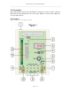
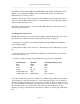
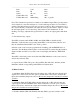
Model 10/12 Control Card Test Fixture 1.0 Description Detcon Model 10/12 Control Card Test Fixture is designed to test the operation of Detcon Model Series 10 and Model Series 12 Control cards. Models covered are 10A, 10B, 10C, 12, 12A, 12B, and 12C. 2.0 Features Reference figure 1 below for feature locations.
Model 10/12 Control Card Test Fixture 1 - Internal power supply and power switch 2 - Sensor power indicator LED (D4) 3 - mA output digital LED meter 4 - Remote alarm reset switch (SW2) 5 - mA input range selector switch and Facilities Module selector (SW1) 6 - mA input adjustment potentiometers (R4 & R24) 7 - mA meter shunt - mA in (JP2) 8 - RS-485 output (TB2) 9 - Fault and alarm relay output LEDs (D5-8, D9-12) 10 - RS-485 Input (TB3) 11 - mA meter shunt - mA out (JP2) 12- Model 10 connector (J1) 13- Mode
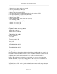
Model 10/12 Control Card Test Fixture Require tools: Digital Volt-Ohm Meter (DVM) Jewelers screwdriver NOTE: These instructions cover testing of the main features of the Model 10 and Model 12 control cards. See the applicable instruction manual for a complete list of program features and detailed operating procedures. 4.
Model 10/12 Control Card Test Fixture Turn SW1 clockwise until ALM1 and ALM2 LEDs on the Model 10 illuminate. Verify that the corresponding alarm LEDs on the test fixture (D6 and D7) also illuminate. Return SW1 to the “4mA” position. If alarms on the control card are programmed for latching, push the alarm reset button to deactivate. Test the Remote Reset button on the test fixture by reactivating the (latched) alarms and then use SW2 to reset.
Model 10/12 Control Card Test Fixture 5 - Check alarm relay outputs. NOTE: Model 10C control cards are 2 alarm devices. Disregard the alarm 3 (D8) LED on the test fixture for this test. FLT, ALM1, and ALM2 LEDs (D5, D6, & D7) will be dimly illuminated when not in alarm. This dim illumination indicates that the normally closed contacts are operating properly. Turn SW1 clockwise until ALM1 and ALM2 LEDs on the Model 10C illuminate.
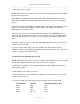
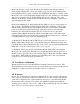
Model 10/12 Control Card Test Fixture Variable R4 & 24 100 Flashing 20.0 Note: The Variable mA position is normally set for 20.0 mA input. These potentiometers can be adjusted to cause the mA input to cover the full range from 0 to 21+ mA. This is useful for checking alarm set points and over-range conditions. The potentiometers are turn. Center the fine potentiometer and adjust the coarse potentiometer to where you want the mA input signal to be. Use the fine potentiometer for fine adjustments.
Model 10/12 Control Card Test Fixture 2mA 4mA 12mA Variable R4 & 24 Variable R4 & 24 CAL 00 50 (±1) 100 100 flashing 02.0 04.0 12.0 20.0 20.1 or greater Note: The Variable mA position is normally set for 20.0 mA input. These potentiometers can be adjusted to cause the mA input to cover the full range from 0 to 21+ mA. This is useful for checking alarm set points and over-range conditions. The potentiometers are turn.
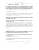
Model 10/12 Control Card Test Fixture Model 10C and 12C control cards. The Model 10C Facilities Module runs different firmware than a Model 10C control card and has a piggy-back board and different face plate and label. Likewise, there is a Model 12C Facilites Module that is a variation on the Model 12C control card. The Facilites Module makes use of two RS485 ports. The Model 10C control card makes use of only the RS485 OUT port.