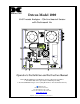
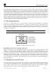
Detcon Model 1000 H2S Process Analyzer - Electrochemical Sensor with Instrument Air PART NO. MODEL NO. SERIAL NO. INPUT VOLTAGE FREQUENCY CURRENT LOAD AREA CLASSIFICATION detcon inc. 3200 A-1 Research Forest Dr. The Woodlands, TX 77381 www.detcon.com AIR INLET SAMPLE FLOW AIR FLOW SAMPLE PRESSURE 10 PSIG (CONSTANT) SAMPLE INLET Operator’s Installation and Instruction Manual Detcon Model 1000 Series H2S Analyzer consists of two major assemblies: 1.
Mdl 1000 H2S E-Chem / Inst.
Mdl 1000 H2S E-Chem / Inst. Air Table of Contents 1. Introduction.............................................................................................................................................. 1 1.1 DM-624 Sensor .................................................................................................................................... 1 1.2 Electrochemical Sensor ........................................................................................................................
Mdl 1000 H2S E-Chem / Inst. Air Table of Figures Figure 1 DM624 Sensor ....................................................................................................................................... 1 Figure 2 Construction of Electrochemical Sensor................................................................................................ 2 Figure 3 Functional Block Diagram .....................................................................................................................
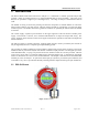
Mdl 1000 H2S E-Chem / Inst. Air 1. Introduction The Detcon Model 1000 Series H2S Process Analyzer is a 110/220VAC or 24VDC powered analyzer that provides a select gas sample mixture to an on-board DM-624 H2S gas sensor assembly. The range of gas analysis can span from 0-10ppm up to 0-20,000ppm (2%). The range of analysis is determined at time of order. The NEMA 7X rating is achieved by housing all electronic components in suitable NEMA 7X enclosures.
Mdl 1000 H2S E-Chem / Inst. Air Detcon MicroSafe™ Model DM-624, toxic sensors are non-intrusive “Smart” sensors designed to detect and monitor for H2S gas in the ppm range. A primary feature of the sensor is its method of automatic calibration, which guides the user through each step via instructions displayed on the backlit LCD. The sensor features field adjustable, fully programmable alarms and provides relays for two alarms plus fault as standard.
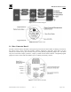
Mdl 1000 H2S E-Chem / Inst. Air Figure 3 Functional Block Diagram Figure 4 DM-624 Control Circuit 1.4 Base Connector Board The base connector board is mounted in the explosion proof enclosure and includes: the mating connector for the control circuit, reverse input and secondary transient suppression, input filter, alarm relays, lug less terminals for all field wiring, and a terminal strip for storing unused programming jumper tabs.
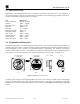
Mdl 1000 H2S E-Chem / Inst. Air 1.5 Interference Data DM-624 series electrochemical H2S sensors are subject to interference from other gases. This interaction is shown in the following table as the relation between the amount of the interfering gas applied to the sensor, and the corresponding reading that will occur (in ppm).
Mdl 1000 H2S E-Chem / Inst. Air 2. Specifications Sensor Type Electrochemical cell Measurement Range 0-10ppm H2S, up to 0-10,000ppm H2S Accuracy/Repeatability ±10% of reading or ±0.5ppm, whichever is greater Response/Clearing Time T80 < 1 minute Operating Temperature -40°F to +122°F: -40°C to +50°C Outputs Linear 4-20mA DC; RS-485 Modbus™; 3 relays (alarm 1, alarm 2, and fault), Contacts rated 5 amps Input Voltage 110~220VAC; 10~30VDC Power Consumption 700mA (16.
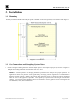
Mdl 1000 H2S E-Chem / Inst. Air 3. Installation 3.1 Mounting Securely mount the Model 1000 analyzer panel or NEMA 4 enclosure (optional) in accordance with Figure 7. Figure 7 Unit Dimensions 3.2 Gas Connections and Sampling System Notes 1. Install a length of tubing from the desired sample point to the sample input port (as shown in Figure 8. Sample draw tubing should be 316 stainless steel of ¼" O.D. NOTE: A constant pressure of 10±2psig should be provided to the analyzer for proper operation.
Mdl 1000 H2S E-Chem / Inst. Air PART NO. MODEL NO. SERIAL NO. INPUT VOLTAGE FREQUENCY CURRENT LOAD AREA CLASSIFICATION detcon inc. 3200 A-1 Research Forest Dr. The Woodlands, TX 77381 www.detcon.com AIR INLET Instrument Air Inlet Port SAMPLE FLOW AIR FLOW Cal Gas Pressure Gauge SAMPLE PRESSURE 10 PSIG (CONSTANT) SAMPLE INLET Sample Inlet Port Sample Calibrate NOTE: These may be combined into a single vent H2S Vent Sample Bypass and Liquid Rejection Exhaust Vent.
Mdl 1000 H2S E-Chem / Inst. Air Customer Connections INPUT + + 24VDC OUT 2.1A + 24VDC OUT 2.1A + 18-36 VDC IN 18-36 VDC IN + - +24VDC -24VDC (Ground) 117VAC / 24VDC In 4-20mA, RS485, Alarm/Fault Sensor Relays Low Flow Air/ Sample Relays (Optional) SAMPLE FLOW AIR FLOW Figure 9 Installation Wiring Connections 1. For AC powered unit connect 117/220VAC to the terminal connector labeled “VAC IN” (JP8A) inside the explosion-proof enclosure on the upper right.
Mdl 1000 H2S E-Chem / Inst. Air 4. Optional Low Flow Fault Alarm PCA’s for Sample gas and Air are available. They provide a form “C” relay contact (common, normally open and normally closed) rated 1 amp at 30VDC/0.24 amp at 125VAC. Relay contacts are pre-wired to the I/O connector PCB located in the “Power Supply” explosion-proof enclosure and are labeled “FLO FLT1” and “FLO FLT2” respectively (Figure 9). 3.
Mdl 1000 H2S E-Chem / Inst. Air Replace the plug-in control circuit and replace the junction box cover.
Mdl 1000 H2S E-Chem / Inst. Air 4. Start Up Upon completion of all tubing connections and field wiring the Model 1000 Series Process Analyzer is ready for startup. Note that after power is applied, varying readings may occur during sensor warm-up. Allow at least 1 hour for stabilization (24 hours is best). With sample gas and air flowing, apply system power and observe the following normal conditions: a) DM-624 “Fault” LED’s are off.
Mdl 1000 H2S E-Chem / Inst. Air 5. Operating Software 5.1 Programming Magnet Operating Instructions Operator interface to MicroSafe™ gas detection products is via magnetic switches located behind the transmitter faceplate. DO NOT remove the glass lens cover to calibrate or change programming parameters.
Mdl 1000 H2S E-Chem / Inst. Air 5.2.2 Calibration Mode Calibration mode allows for sensor zero and span adjustments. It uses an “AUTO SPAN” sequence with built in diagnostics to ensure adequate sensor response and signal stability. “1-ZERO 2-SPAN” Zero Adjustment Zero is set with no H2S target gases present. “AUTO ZERO” Span Adjustment Span adjustment is performed with a target gas concentration of 10 ppm H2S in nitrogen. concentrations other than 10 ppm may be used.
Mdl 1000 H2S E-Chem / Inst. Air c) Exit back to normal operations by holding the programming magnet over “PGM 2” for 3 seconds, or, the sensor will automatically return to normal operation in 30 seconds. Alarm 1 Level Adjustment The alarm 1 level is adjustable over the range 10% to 90% of range. For hydrogen sulfide gas sensors, the level is factory set at 20% F.S. The menu item appears as: “SET ALM1 @ ### PPM”.
Mdl 1000 H2S E-Chem / Inst. Air 6. Calibration and Maintenance The Model 1000 Series H2S Process Analyzer is calibrated prior to shipment. Only minimal adjustment should be required at time of commissioning. However, it is highly recommended that a zero and span calibration be performed twice in the first week of operation to assure optimum system performance. After that, a recalibration interval of every month is recommended.
Mdl 1000 H2S E-Chem / Inst. Air CAUTION: Verification of the correct calibration gas level setting and calibration span gas concentration is required before “span” calibration. These two numbers must be equal. Span Calibration consists of entering the calibration function and following the menu-displayed instructions. The display will ask for the application of span gas in a specific concentration. The concentration must be equal to the calibration gas level setting.
Mdl 1000 H2S E-Chem / Inst. Air Additional Notes a) Upon entering the calibration menu, the 4-20mA signal drops to 2mA and is held at this level until the sensor returns to normal operation.
Mdl 1000 H2S E-Chem / Inst. Air 8. Programming Features Detcon MicroSafe™ H2S gas sensors incorporate a comprehensive program to accommodate easy operator interface and fail-safe operation. Program features are detailed in this section. Each sensor is factory tested, programmed, and calibrated prior to shipment. Over Range When the sensor detects gas greater than 100% of its range, it will cause the display to flash the highest reading of its range on and off.
Mdl 1000 H2S E-Chem / Inst. Air Code 03 - Read Holding Registers is the only code supported by the transmitter. Each transmitter contains 6 holding registers which reflect its current status.
Mdl 1000 H2S E-Chem / Inst. Air Bit 1 Bit 0 1-Fault is latching 0-Fault is non-latching 1-Fault Relay is energized 0-Fault Relay is not energized The following is a typical Master Query for device # 8: Field Name HEX DEC RTU Slave Address 08 8 0000 1000 Function 03 3 0000 0011 Start Address Hi 00 0 0000 0000 Start Address Lo 00 0 0000 0000 No. of Registers Hi 00 0 0000 0000 No.
Mdl 1000 H2S E-Chem / Inst. Air 10. Display Contrast Adjustment Detcon MicroSafe™ sensors feature a 16 character backlit liquid crystal display. Like most LCDs, character contrast can be affected by viewing angle and temperature. Temperature compensation circuitry included in the MicroSafe™ design will compensate for this characteristic; however temperature extremes may still cause a shift in the contrast. Display contrast can be adjusted by the user if necessary.
Mdl 1000 H2S E-Chem / Inst. Air 13. Troubleshooting Reading higher or lower than anticipated Probable cause: Incorrect sample flow or air flow, degraded cal gas, or needs to be zero and span calibrated. 1. Check for correct sample flow “S→ ” marking 200cc/min. 2. Check for correct air flow “→” marking 500cc/min. 3. Check span gas is same as programmed AutoSpan value. 4. Check Span Calibration gas for valid concentration in nitrogen gas using H2S pull tube. 5. Re-calibrate sensors with known good span gas.
Mdl 1000 H2S E-Chem / Inst. Air 14. Spare Parts Part# 327-000000-000 360-2424GH-030 360-205421-024 943-010013-505 823-101085-882 350-300000-000 348-900000-000 350-523081-02K 308-091000-030 985-240600-384 Description Programming Magnet 24V DC-DC Converter 24 VDC Power Supply Assembly 500 CC Fixed Flow Regulator Genie Membrane Filter 0.
Mdl 1000 H2S E-Chem / Inst. Air Spare Parts DM-624 H2S Sensor Part# Description 942-010212-XXX Calibration Span Gas (XXXppm H2S, balance nitrogen) (Where XXX denotes the gas level – 010 = 10ppm, 025 = 25ppm, 050 = 50ppm) 926-245502-XXX Transmitter Module XXXppm Range (for H2S Alcohol Free gas sensor) (Where XXX denotes the Range – i.e.: 005 = 0-5ppm, 010 = 0-10ppm, 020 = 0-20ppm, etc.) 404-0H2S3H-NXX Sensor Housing Assembly (Where XX denotes Range – i.e.: N5K = 0-5000ppm, N1P = 0-2%, N2P = 0-2%, etc.
Mdl 1000 H2S E-Chem / Inst. Air 15. Warranty Detcon Inc., as manufacturer, warrants under intended normal use each new Model 1000 Series H2S Process Analyzer gas detection system to be free from defects in material and workmanship for a period of one year from the date of shipment to the original purchaser. All warranties and service policies are FOB the Detcon Inc. facility located in The Woodlands, Texas. Sensor Transmitter Detcon, Inc.
Mdl 1000 H2S E-Chem / Inst. Air 16. Flow Diagrams PART NO. MODEL NO. SERIAL NO. INPUT VOLTAGE FREQUENCY CURRENT LOAD AREA CLASSIFICATION detcon inc. AIR INLET 3200 A-1 Research Forest Dr. The Woodlands, TX 77381 www.detcon.com AIR AIR FLOW SAMPLE FLOW SAMPLE PRESSURE 10 PSIG (CONSTANT) Sample Input SAMPLE INLET SAMPLE Vent CALIBRATE Vent Vent Figure 16 Unit Flow Diagram Model 1000 H2S E-Chem w Instrument Air Rev. 1.
Mdl 1000 H2S E-Chem / Inst. Air 17. Wiring Diagram Red 18AWG 30 + + 18-36 VDC IN 24VDC OUT 2.
Mdl 1000 H2S E-Chem / Inst. Air Appendix C Revision Log Revision Date 0.0 10/31/09 1.0 06/13/11 1.1 09/19/11 Changes made Manual Created Updated drawings and Spare parts list. Added approvals column to revision log Update to notation in section 3.3 regarding VDC input to match wiring diagram Approvals BM LU LU Shipping Address: 3200 A-1 Research Forest Dr., The Woodlands Texas 77381 Mailing Address: P.O. Box 8067, The Woodlands Texas 77387-8067 Phone: 888.367.4286, 281.367.4100 • Fax: 281.292.