detcon inc. Detcon Model 10 Single Channel Digital Control Module Operator’s Installation & Instruction Manual September 11, 2007 • Document #2160 • Version 1.4 phone 888-367-4286, 281-367-4100 • fax 281-292-2860 • www.detcon.com • sales@detcon.
Table of Contents 2.0 Description 2.1 Specifications 2.2 Controller Models 2.3 Alarm Functions and Controller Configuration 2.4 Controller Operation and Menu Selections 2.5 Power Input Options 2.6 Analog 4-20 mA Signal Input/Output 2.7 RS-485 Modbus™ Specifications 2.8 Fault Circuit Functions 2.9 Other Features 2.10 Controller Calibration 2.11 Warranty & Service Policy Model 10 Single Channel Digital Control Module PG.
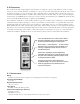
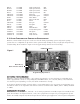
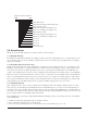
2.0 DESCRIPTION Detcon Model 10 single channel digital control modules are designed to supervise and display the status of a single remote gas sensor assembly. Modules are available for a variety of toxic and combustible gases. Model 10 Series control modules are designed to operate on an input voltage of 24 VDC and are compatible with a complete line of Detcon enclosures and mainframe hardware assemblies.
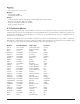
Warranty One year Five year fixed fee service policy Outputs Analog 4-20 mA DC Serial RS-485 Modbus™ Relays Contacts include common, normally open, and normally closed for three alarms Resistive load: 5A, 250 VAC; 5A, 30 VDC Inductive load: 2A, 250 VAC; 2A, 30 VDC Max. operating current: 5A 2.2 CONTROLLER MODELS The table below provides a list of model numbers of the Series 10 Controller, the target gas and gas formula, and the standard range for that gas.
HBr-10 HCL-10 HCN-10 HF-10 CH30H-10 CH3SH-10 NO-10 NO2-10 O3-10 COCL2-10 PH3-10 SiH4-10 SO2-10 C4H8S-10 C4H4S-10 C4H6O2-10 C2H3CL-10 0-30 PPM 0-30 PPM 0-30 PPM 0-10 PPM 0-100 PPM 0-100 PPM 0-100 PPM 0-5 PPM 0-1 PPM 0-1 PPM 0-5 PPM 0-50 PPM 0-20 PPM 0-100 PPM 0-100 PPM 0-100 PPM 0-100 PPM Hydrogen Bromide Hydrogen Chloride Hydrogen Cyanide Hydrogen Fluoride Methanol Methyl Mercaptan Nitric Oxide Nitrogen Dioxide Ozone Phosgene Phosphine Silane Sulfur Dioxide Tetrahydrothiophene Thiophane Vinyl Acetate Viny
is to have the fault relay normally energized so that in the event of a power failure to the control module card, the fault relay will de-energize causing its relay contacts to change state, thereby creating a fault output. It must be noted that when an alarm relay is jumper programmed as normally energized, the contact outputs, normally open and normally closed, become reversed. The normally open contact becomes the normally closed and vice versa.
To enter the Program Menu press and hold the front panel switch for 10 seconds until the display reads Pr then release. Momentarily pressing the switch again after this will scroll through the program options.
2.4.7 Test Mode This function (tE) will cause a simulation of applying a full scale gas sample that will take the display through an incremental count up to the top of the range and back down, activating alarms at the programmed set points and allowing verification of alarm outputs, as well as the overange flashing feature. 2.5 POWER INPUT OPTIONS Standard operating input power of the Model 10 control module is 24 VDC unless 12 VDC is specified at time of order.
Register 40005 Status Bits MSB LSB Fault alarm status Fault alarm latching/non-latching mode Alarm 1 alarm status Alarm 1 latching/non-latching mode Alarm 1 ascending/descending mode Alarm 2 alarm status Alarm 2 latching/non-latching mode Alarm 2 ascending/descending mode Not used Not used Not used Not used Test mode status 2.9 OTHER FEATURES Model 10 control modules include other features which are discussed below. 2.9.
4. Alarm 1 is set to 20% of the default range. 5. Alarm 2 is set to 50% of the default range. 6. The RS-485 address is set to 01h. 2.10 CONTROLLER CALIBRATION The 4-20 mA output of the Model 10 control module is calibrated at the factory and should require no further adjustment. If under some special circumstance calibration is required, use the following instructions. To calibrate the controller you will need an extender card and have to be able to simulate a 4mA input and a 20mA input. 2.10.