Model 10C Single Sensor Control Module Operator’s Installation and Instruction Manual Covers all Model 10C Control Modules DETCON, Inc. 3200 Research Forest Dr., The Woodlands, Texas 77387 Ph.281.367.4100 / Fax 281.298.2868 www.detcon.com January 29, 2009 • Document #3256 • Revision 0.
Model 10C Blank Page Shipping Address: 3200 A-1 Research Forest Dr., The Woodlands Texas 77381 Mailing Address: P.O. Box 8067, The Woodlands Texas 77387-8067 Phone: 888.367.4286, 281.367.4100 • Fax: 281.292.2860 • www.detcon.com • sales@detcon.
Model 10C Table of Contents 1.0 Description................................................................................................................................................ 1 1.1 Display Function .................................................................................................................................. 2 1.2 Alarm Functions ................................................................................................................................... 2 1.2.
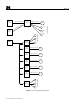
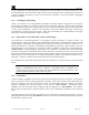
Model 10C 4-20mA Current Output 5 48 RS D MO SC BU 10C Controller 4-20mA Current Input Sensor M OM Fault Alarm1 Modbus HOST Facilities Module 10C Controller 4-20mA Current Input 10C Controller 4-20mA Current Input 10C Controller 4-20mA Current Input 10C Controller 4-20mA Current Input 10C Controller 4-20mA Current Input Relay Outputs Sensor Sensor Sensor Sensor Sensor ZONE 2 OUTPUTS Modbus HOST ZONE 1 OUTPUTS Alarm2 OUTPUT DEVICES Master Controller Figure 1 System Applicat
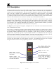
Model 10C 1.0 Description The Detcon Model 10C single sensor control module (10C Controller) is designed to supervise and display gas concentration and the status of a remote gas sensor assembly. Mod 10C Controllers may be configured for a variety of toxic and combustible gases. The 10C Controller is designed to operate on a nominal input voltage range of 12 VDC to 24VDC and is compatible with a complete line of Detcon enclosures.
Model 10C 1.1 Display Function The main purpose of the 10C Controller’s 4-character display is to show the gas concentration reading at all times. The reading is given in numeric form and with the desired units, as converted from the current input signal of the attached gas sensor. Upon operation of the pushbuttons, the display also allows viewing gas type and units very simply, and with further manipulation allows viewing of any configurable setting. 1.
Model 10C A typical application of an Energized relay could be the use of the Fault Relay in a Fail-Safe Fault Circuit. The loss of functionality of the Controller would cause the coil to De-Energize, thus creating a Fault output to the receiving equipment, for instance: if power is lost to the 10C Controller, or if the 10C module is unplugged from the live chassis. 1.2.
Model 10C 1.3 Fault Circuit Functions How the 10C Controller responds to a fault condition is determined by the configuration programmed into the controller. Faults can be programmed as latching or non-latching, energized or de-energized, and silenceable or non-silenceable operation. Any combination of these settings, and the set-point threshold at which a fault will trigger, can be programmed to provide setups for almost any contingency.
Model 10C 1.4 RS-485 Modbus™ The 10C Controllers feature Modbus™ compatible communications protocol and are addressable via the programming menu for multi-point communications. Communication is two wire, half-duplex, with the Model 10C controller set up as a slave device. A master controller can address a maximum of 255 different 10C Controllers.
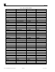
Model 10C Table 1 10C Controller Models Model # AsH3-10 Br2-10 B2H6-10 CG–10 CH20-10 CH30H-10 CH3SH-10 CLO2-10 CL2-10 CO-10 COCL2-10 CO2-10 CS-10 CS2-10 C2H2-10 C2H3CL-10 C2H30-10 C2H4-10 C2H4O-10 C2H5OH-10 C2H6S-10 C3H3N-10 C3H5OCL-10 C4H4S-10 C4H6-10 C4H8S-10 C4H6O2-10 F2-10 GeH4-10 HBr-10 HCL-10 HCN-10 HF-10 H2S-100 H2-10 H2-10 NH3-10 NO-10 NO2-10 N2H4-10 O2-10 O3-10 PH3-10 SiH4-10 SO2-10 10C Control Module Instruction Manual Target Gas Arsine Bromine Diborane Combustible Gases Formaldehyde Methanol
Model 10C 2.0 Operator Interface The 10C Controller is configured by use of the front panel display and pushbuttons. The 10C Controller User Interface Menu System allows the user to set various parameters associated with the sensor: Gas type, Range, Units, Alarm settings, and Modbus ID.) Navigation through the menu system is accomplished by use of the 10C Controller’s Front Panel Pushbuttons: the Enter key “ENT”, the Escape key “ESC”, the Up key “×” (or “RESET”), and the Down key “Ø” (or “SLNC”).
Model 10C 2.2 Program Mode While in Normal Operation with Concentration displaying, pressing the “ENT” pushbutton and holding it for about three seconds allows the Program Mode to be accessed. While in the Program Mode, the left pushbuttons have the meaning “×”and “Ø”which allow moving back and forth or up and down through the menu and for changing values up and down.
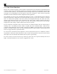
Model 10C JP1: “LPBAK” jumper (normally open- only shunt for testing). SW1: Access/Normal Switch Figure 3 Board Assembly Picture of 10C Controller 10C Control Module Instruction Manual Rev. 0.
Model 10C 3.0 Normal Operation 3.1 Display Gas Concentration and Alarm Condition In normal operation, the 10C Controller display continuously shows the sensor’s gas concentration reading (normally “00”). Pressing the “ENT” pushbutton and holding it down for about three seconds will take the user into the Program Mode Menu. The “RESET” pushbutton will reset the alarm(s) if the 10C Controller has been configured properly, and all conditions for Alarm Reset have been satisfied.
Model 10C 3.2 Displaying Gas Type and Units While in Normal mode, and while the Gas Concentration is being displayed, the “ESC” button can be pressed to momentarily display the Gas Type and the Units; for instance: H2S and ppm. 3.3 Program Status While in Normal mode, and while the Gas Concentration is being displayed, the ability to view the configuration or “Program Status” is always available to all operators.
Model 10C 4.0 Program Mode Program Mode is only accessible with the “ACCESS/NORM” Switch (SW1) in the “ACCESS” position. With the switch in the “NORM” position, only the Program Status Function is available, and only the reading of configuration values is possible. The “ACCESS/NORM” switch is located in the lower left-hand corner on the PCA just behind the faceplate, and can be accessed by removing the PCA from the card rack.
Model 10C Table 3 List of Gas Types Gas Type H2S LEL O2 CO CO2 Cl2 NH3 H2 NO NO2 SO2 VOC AsH3 B2H6 C2H2 C2H3O C2H3Cl C2H4 C2H4O C2H5OH C2H6S C3H3N C3H5OCL C4H4S C4H6 C4H6O2 C4H8S CH2O CH3OH CH3SH COCl2 CS2 F2 GeH4 HBr HCl HCN HF N2H4 PH3 SiH4 Br2 CLO2 O3 Target Gas Hydrogen Sulfide LEL Combustible Gases Oxygen Carbon Monoxide Carbon Dioxide Chlorine Ammonia Hydrogen Nitric Oxide Nitrogen Dioxide Sulfur Dioxide Volatile Organic Com Arsine Diborane Acetylene Acetaldehyde Vinyl Chloride Ethylene Ethylene Ox
Model 10C NOTE: While the term “LEL” is used here as a Gas Type, it must be understood that the term stands for Lower Explosive Limit and implies a Range for a combustible gas without being specific about which explosive gas. If the gas is Methane (CH4), the LEL is about 5% by volume of Methane in Air. Therefore, 100% LEL is equivalent to about 5% equivalent methane in air by volume. When the chosen Gas Type is found, the “ENT” pushbutton can be used to select it.
Model 10C 4.3 Set Units Set Units provides a means to adjust the units of measure for the Range selected. The Units should match the units of measure of the associated sensor. The menu item appears as: “UNITS SET”. From the “UNITS SET” display use the “ENT” pushbutton to enter the function. The display will flash the units of measure currently set. Use the “×” and “Ø” pushbuttons to move through the different units of measure available.
Model 10C The display will stop flashing and the selected Set-Point values will be solidly displayed. Pressing the “ENT” pushbutton again will move to the next parameter in the list. Note that when setting the Set-Point of the Alarms that the reading is directly proportional to the Range. Therefore, if the range is set to 500ppm the Set-Point display will step by the increment of 5ppm. That is, for every press of the “×” or the “Ø” pushbutton, the display will increase or decrease by 5ppm.
Model 10C 4.5 Modbus™ Set Set Modbus™ provides a means to set the unique identifying Modbus™ Address. The Address is also known as the “ID” or “Modbus RTU ID”. The menu item appears as: “MODBUS SET”. From the “MODBUS SET” display press the “ENT” pushbutton to enter the function. To enter “ID Set” function, press the “ENT” pushbutton while the “ID Set” display is scrolling. The display will flash the current Modbus™ ID Address in Hexadecimal format.
Model 10C 4.7 Test The 10C Controller “TEST” provides a means of checking the external alarm system by artificially setting off Relay Outputs without having to force them on/off through the external sensor input to the Controller. The “TEST” consists of an internal test variable that starts at zero and increases to full-scale range and then decreases back to zero. The internal variable is fed into the internal Controller processing as if it were an external sensor signal.
Model 10C 5.0 Special Configuration (Technician Access) Only personnel who are technically trained to configure the equipment should be allowed to access some of the features built-in to the 10C controller. There are three levels of access: NORMAL Normal Operation Access (See section 3.0 on “Normal Operation”) ACCESS Program Mode Access (See section 4.
Model 10C From the “TRIM INPUT” display the technician can use the “ENT” pushbutton to enter the function. The display will scroll “SET 0mA”. Apply 0 mA to the 10C Controller’s 4-20mA current input. Removal of the input current wire to the sensor is the same as applying 0mA. Once 0mA is applied, press the “ENT” pushbutton to accept the value, the display will scroll “0mA Done”. Press the “ENT” pushbutton again, and the display will scroll “SET 20mA”. Apply 20.
Model 10C NOTE: This mode does not automatically time-out and must be exited or power-cycled to return to normal operation. 5.3 Default Settings NOTE: The Default Settings function is only accessible in Technician Access Mode. Each and any setting within the 10C Controller should be manually changeable to valid values. This feature sets all configuration values to default state at once, including the trim coefficients.
Model 10C 6.0 Calibration The 10C Controller’s conversion, of input current to a displayed value, can be trimmed up or down. Likewise, the 10C Controller’s output current can be trimmed so that the Master Controller can register what is on the 10C Controller’s display. Each of the 4-20mA analog current input and the 4-20mA analog current output of the 10C Controller may be trimmed independently. Both are calibrated at the factory and should require no further adjustments.
Model 10C 7.0 Specifications Input Power 9 VDC to 28VDC (For use in nominal 12VDC or 24VDC typical systems) 300mA Maximum (Including Sensor) 3W Maximum (Including Sensor) Operating Temperature –40°C to +70°C Humidity: 10 to 95% Non-condensing Range Configurable: From 1 to 25 in increments of 1 From 25 to 100 in increments of 5 From 100 to 1000 in increments of 50 From 1000 to 9999 in increments of 500 Accuracy/Repeatability Sensor input current conversion to 10C Displayed reading: ±1%F.S.
Model 10C 8.0 Warranty and Service Policy Detcon, Inc., as manufacturer, warrants each new Model 10 series digital electronic control module to be free from defects in material and workmanship under intended normal use for a period of one year from date of shipment to the original purchaser. Detcon, Inc., additionally provides for a fixed fee repair/replace service policy which covers Model 10 series digital control modules for a period of five years.
Model 10C 8.1 Revision Log Revision 0.0 Date 01/13/2009 10C Control Module Instruction Manual Changes made None Initial release Rev. 0.