
Manual

Model 10C
3.0 Normal Operation
3.1 Display Gas Concentration and Alarm Condition
In normal operation, the 10C Controller display continuously shows the sensor’s gas concentration reading
(normally “00”). Pressing the “ENT” pushbutton and holding it down for about three seconds will take the
user into the Program Mode Menu. The “RESET” pushbutton will reset the alarm(s) if the 10C Controller has
been configured properly, and all conditions for Alarm Reset have been satisfied. The “SLNC” Button will
silence the alarm(s) if the 10C Controller has been configured properly, and the alarm silence conditions have
been satisfied.
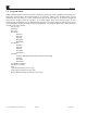
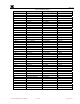
Table 2, Input Current Below 4mA
Table 2, Input
Current Below 4mA
Input Current (mA) Display
0-1.8 SENS
1.8-2.4 CAL
2.40-2.56 -9
2.56-2.72 -8
2.72-2.88 -7
2.88-3.04 -6
3.04-3.20 -5
3.20-3.36 -4
3.36-4.00 00
If the current-loop input reads below the Fault Set-Point, the sensor is in Fault. The 10C Controller will
activate the Fault Alarm relay and the Fault LED will activate to indicate the Fault condition.
, reveals what the display should say for input current less than 4mA. If the current-loop
input measures nominally 2.0mA, the Sensor is in Calibration Mode and the 10C Controller will display the
text ‘CAL’ and the Fault LED will be activated. Very low input current should cause the display to say
‘SENS’ to indicate Sensor Fault. In either case, the Fault Relay will be set, according to the configuration, to
convey a fault status. Note that if the Fault Relay is configured as normally energized, the relay coil will de-
energize to convey a fault status. If the Fault Relay is configured as normally de-energized, the relay coil will
energized to convey a fault status.
When an alarm is triggered the corresponding alarm LED will illuminate to indicate the alarm (Alarm 1 and/or
Alarm 2). The corresponding relays will also be set to convey the appropriate status. If the associated alarm
relay is configured as normally energized, the relay coil will de-energize to convey an alarm status. If the
alarm relay is configured as normally de-energized, the relay coil will energize to convey an alarm status.
In normal operation, the 4-20mA current output corresponds directly with the Sensor 4-20mA input. The RS-
485 Modbus™ serial communications provides the current gas reading and complete fault status when polled
by the Master Controller.
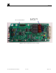
If Program Mode is accessible because of the “ACCESS/NORM” Switch (see location of SW1 in
) in the “ACCESS” position, then the user can hold down the
“ENT” key to enter the Program Mode and internal configuration values can be changed. If the
“ACCESS/NORM” Switch (SW1) is in the “NORM” position then only the review of Program Status (see
section 3.2) is accessible.
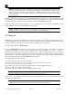
Figure 3
Board Assembly Picture of 10C Controller
10C Control Module Instruction Manual Rev.0.B Page 10 of 25