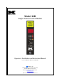
Model 12B Single Channel Control Module Operator’s Installation and Instruction Manual Covers all Model 10C Control Modules DETCON, Inc. 4055 Technology Forest Blvd. Suite 100, The Woodlands, Texas 77381 Ph.281.367.4100 / Fax 281.298.2868 www.detcon.com April 25, 2012 • Document #1953 • Revision 1.
Model 12B This page left intentionally blank 12B Control Module Instruction Manual ii
Model 12B Table of Contents 1.0 Description .......................................................................................................................................... 1 2.0 Specification........................................................................................................................................ 2 3.0 Controller models ............................................................................................................................... 2 4.
Model 12B This page left intentionally blank Shipping Address 4055 Technology Forest Blvd. Suite 100,., The Woodlands Texas 77381 Mailing Address: P.O. Box 8067, The Woodlands Texas 77387-8067 Phone: 888.367.4286, 281.367.4100 • Fax: 281.292.2860 • www.detcon.com • sales@detcon.
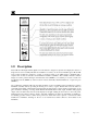
Model 12B 1.0 Description Detcon Model 12B single channel digital control modules are designed to supervise and display the status of a single remote sensor assembly. Modules are available for a variety of toxic and combustible gases. Model 12B series control modules are designed to operate on an input voltage of 24 VDC and are compatible with a complete line of Detcon enclosures and mainframe hardware assemblies.
Model 12B 2.0 Specification Range 0-99 ppm/% is typical but varies according to application Accuracy/Repeatability ± 2% F.S.
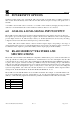
Model 12B CO-12B SO-12B NO-12B CL-12B CD-12B H2-12B NX-12B 4.0 CO carbon monoxide SO2 sulfur dioxide NO2 nitrogen dioxide CL2 chlorine CLO2 chlorine dioxide H2 hydrogen NO nitric oxide 0 - 100 ppm 0 - 100 ppm 0 - 100 ppm 0 - 10.0 ppm 0 - 10.0 ppm 0 - 100 ppm 0 - 100 ppm 0 - 100 0 - 200 0 – 500 0 – 999 Alarm functions and settings Model 12B control modules incorporate several user selectable alarm programming options that are accomplished via rotary dip switches or jumper tabs.
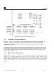
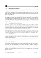
Model 12B Figure 1 Alarm Set switches and Alarm Relay Jumpers 4.2 Latching or non-Latching Relays All alarms — alarm 1, 2, 3, and fault — can be jumper programmed to operate as latching or nonlatching. If an alarm is programmed to latch, its corresponding relay and LED indicator, once activated, will stay activated until the reset button is pressed (assuming, of course, that alarm conditions have cleared).
Model 12B 4.4 Energized or De-energized All alarm relays — alarm 1, 2, 3, and fault — can be jumper programmed as normally energized or normally de-energized. The standard is de-energized. However, a relay can be programmed as energized to provide application specific features. A normally energized relay will de-energize when in alarm.
Model 12B 5.0 POWER INPUT OPTIONS Standard operating input power of the Model 12B control module is 24 VDC unless 12 VDC is specified at time of order. All of the circuitry of the 12B control module, with the exception of relays, will operate on 12 or 24 VDC. A 24 VDC control module can be converted to a 12 VDC control module by changing the relays. If this is desired, it is recommended that the control modules be returned to Detcon to be converted. 6.
Model 12B 8.0 FAULT CIRCUIT FUNCTIONS Model 12B control modules feature fail safe supervisory circuits designed to assure maximum reliability in system performance. A fault condition will cause the fault LED to illuminate and the fault relay to actuate. The exception to this is if the fault relay is jumper-programmed as normally energized, a loss of external 24 VDC power or the internal 5 VDC supply will cause the relay to de-energize but the LED will not illuminate.
Model 12B To program the load bypass circuit for either of the conditions described above: place a jumper tab on pins 2 and 3 (center and right) of the jumper location labeled JP-21. When the 12B control module is used in conjunction with a Detcon TP or FP series sensor, and is being powered by the 12B control module, the jumper tab should be placed on pins 1 and 2 (left and center) of the jumper location. 9.
Model 12B 9.2 Display/Alarm Test To perform the display/alarm test, press and hold the alarm reset button for about five seconds until the fault LED illuminates. Next, press and release the alarm reset button twice. The alarm 2 LED will illuminate indicating that this test has been selected. The test will begin automatically within five seconds. Normal operation resumes when the test is complete.
Model 12B 10.2 Range Configuration Jumpers The applicable range of the 12B control module is factory set according to its corresponding sensor. However, the control module range of detection can be changed if a particular application should warrant it. Range selection is accomplished via configuration jumpers. Use the table below to determine the proper con figuration. See Figure 1 for applicable jumper locations. Range 0 - 1.0 0 – 10 0 - 25 (O2) 0 – 25 0 – 50 0 - 10.0 0 - 25.0 (O2) 0 - 25.0 0 - 50.
Model 12B 10.
Model 12B Appendix C Revision History Revision 1.3 1.4 Date 10/18/10 04/25/12 Changes made Prior release Converted to MS Word format from Quark Removed notation of customer replaceable relays. Corrected Modbus specifications. 12B Control Module Instruction Manual Rev 1.