
Instruction Manual
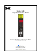

Model 12B
12B Control Module Instruction Manual Rev 1.4 Page 6 of 12
5.0 POWER INPUT OPTIONS
Standard operating input power of the Model 12B control module is 24 VDC unless 12 VDC is specified at
time of order. All of the circuitry of the 12B control module, with the exception of relays, will operate on 12 or
24 VDC.
A 24 VDC control module can be converted to a 12 VDC control module by changing the relays. If this is
desired, it is recommended that the control modules be returned to Detcon to be converted.
6.0 ANALOG 4-20 MA SIGNAL INPUT/OUTPUT
Model 12B control modules receive an analog 4-20 mA signal input corresponding to the range of detection.
The signal is processed through an analog to digital converter and is calibrated so that a 4 mA input will
provide display readout of “0”. This circuitry is factory set. Should adjustment become necessary, the analog
to digital converter can be fine-tuned via the input zero potentiometer (PT1).
Model 12B control modules feature a discreet 4-20 mA signal output corresponding to the range of
detection. This feature is factory set. Should adjustment become necessary, the digital to analog converter can
be calibrated via the output zero potentiometer (PT3), and the output span potentiometer (PT2).
7.0 RS-485 MODBUS™ FEATURES AND
SPECIFICATIONS
Model 12B control modules feature Modbus™ compatible communications protocol and are addressable via
rotary dip switches for multi-point communications. Communication is two-wire, half duplex, with the 12B
control module set up as a slave device. The communications is Modbus RS-485 with 19200 Baud, 8 data bits,
no parity, and 1 stop bit. A master controller up to 4000 feet away can theoretically poll up to 256 different
12B control module cards. This number may not be realistic in harsh environments where noise and/or wiring
conditions would make it impractical to place so many devices on the same pair of wires. If a multipoint
system is being utilized, each 12B control module should be set for a different address. Typical address
settings are: 01, 02, 03, 04, 05, 06, 07, 08, 09, 0A, 0B, 0C, 0D, 0E, 0F, 10, 11, etc.
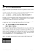
Model 12B control module ID numbers are set via SW11 and SW12. For example, to set the ID number to 01,
set the most-significant-bit rotary dip switch (SW11) to 0, and the least-significant-bit rotary dip switch
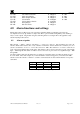
(SW12) to 1. The following register list describes the parameters available from the 12B control module:
40000
Range
40001
Reading
40002
Alarm 1 Set Point
40003
Alarm 2 Set Point
40004
Alarm 3 Set Point