
User Manual


1600/6400-N4X-RD
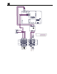
TB1
3
2
1
White 18AWG
Green 16AWG
Black 18AWG
Red 18AWG
White 22AWG
Purple 22AWG
Purple 22AWG
White 22AWG
Black 18AWG
Neutral (L2)
VAC (L1)
Customer Supplied Power
Interface Connections
Legend:
Pre-Wired
Customer Wired
O
I
2A
24VDC Power
Supply
123456
2
-
1 Gnd
L1N
+
NFS40-7624
P1
J1
J1
+
Red 18AWG
Black 18AWG
8
7
6
Ground
A
B
RS-485
5
4
RESET
S2
6400 Controller PCB
Serial Communications
No Comm
VDC IN
RS-485
Input
C
NO
NC
Fault Relay PCB
PCB
S
B
A
+ -
A
B
S
Output
S1
RV1
J4 J3
J3 J7
J1
8 7 6 5 4 3 2 1
1 2
Remote Alarm
Reset PCB
RS-232 I/O
2
1
SW1
Gray 18AWG
Gray 18AWG
Remote Alarm
Reset Switch
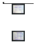
Figure 2 Interconnect Wiring
4.0 Startup
Before applying power, make sure that all wiring is terminated correctly.
NOTE: Applying power with devices hooked up incorrectly may cause damage.
Turn the AC Breaker switch to the ON position. Verify that the main touch-screen LCD comes up displaying
gas readings on the display. You should also verify that the Controller module is being polled by observing a
sequence of blinking LED’s on the backside of the remote display’s control module. Check to make sure these
display readings are identical to those at the Model 1600/6400 Controller.
1600/6400-N4X-RD- Instruction Manual Rev. 1.0 Page 3 of 16