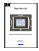
Model 1600A-N1P NEMA 1 Control Panel Operator’s Installation and Instruction Manual DETCON, Inc. 3200 Research Forest Dr., A-1 The Woodlands, Texas 77381 Ph.281.367.4100 / Fax 281.298.2868 www.detcon.com August 10, 2009 • Document # 3438 • Revision 0.
1600A-N1P Page intentionally blank 1600A-N1P Instruction Manual ii
1600A-N1P Table of Contents 1.0 2.0 2.1 2.2 2.3 3.0 3.1 3.2 3.3 3.4 3.5 3.6 4.0 4.1 Introduction .............................................................................................................................................1 System Configuration .............................................................................................................................2 Hardware Configurations ..................................................................................................
1600A-N1P Figure 1 Block Diagram ....................................................................................................................................... 1 Figure 2 System Configurations........................................................................................................................... 2 Figure 3 Unit Mounting and Dimensional............................................................................................................ 4 Figure 4 AC/DC Inputs .............
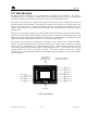
1600A-N1P 1.0 Introduction The Detcon Models 1600A-N1P is a “user-configurable” multi-channel alarm controller. The 1600A is configurable for up to 16 channels. Through the use of I/O modules the 1600A can receive analog inputs consisting of 4-20mA, and can alternatively poll serial sensors via RS-485 Modbus™ RTU. The 1600A-N1P controller uses a modular design approach that allows the user to customize the selection of stand-alone input and output modules.
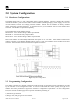
1600A-N1P 2.0 System Configuration 2.1 Hardware Configurations The Model 1600A-N1P is a “user configurable” alarm controller platform. The basic 1600A-N1P Controller includes the NEMA 1 panel enclosure with Controller Module (including display), Power Supply, two AC and one DC breakers, and DC over-voltage protection module. NOTE: The I/O modules are factory installed unless specifically instructed otherwise. A maximum of two (2) I/O modules will fit on the standard N1P enclosure.
1600A-N1P 3) Alarm level(s) for each gas channel 4) Tag Name for each channel 5) Assignment and set-up information for each relay contact NOTE: The set-up configuration is fully field-programmable and can easily be executed by the user in the field by following the instructions within this Operators Manual. Modifications to the set-up configuration are expected to take place at the customer’s site due to requirement changes and/or system expansions. 2.
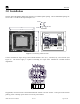
1600A-N1P 3.0 Installation Securely mount the Model 1600A-N1P enclosure on a suitable panel opening. The recommended opening cutsize is 9”W X 7.25”H and the required depth is 16”. 0.375" R0.109" 0.218" 10.5" Slot Detail 9.75" Model 1600A-N1P Multi-Channel Gas Detection Control System 2A 3.
1600A-N1P A B + RESET A B C NO NC Where applicable, connect the RS-485 wiring from remotely located I/O devices to the terminals located on the Back Panel. These terminals are labeled RS-485 “A” (+), “B” (–), and “Shld” (shield) for primary RS-485 communication (Figure 5). RS-485 wiring should consist of a two conductor, shielded twisted pair (Belden cable P/N 9841 is recommended). Also available are two output terminal blocks to provide 24VDC to external RS-485 devices.
1600A-N1P 3.1 1600A Interface Board The 1600A Interface PCA is connected to a set of Terminal Blocks on the DIN Rail (Figure 6 1600A Interface PCA and Figure 7 Interconnect Wiring Diagram.) The Terminal Blocks are labeled “NO COMM” “C”, “NO” and “NC”. The 1600A Interface PCA, mounted on the inside of the top panel of the enclosure, will de-energize the on-board relay in the event there is a ‘No Communication Fault’ condition with any activated device.
1600A-N1P 1600A Interface PCA (located on underside of 1600A-N1P Top Panel) LEDS: RST —This LED is normally off. It glows red when the external reset switch is pressed FAULT —This LED is normally red. NO COMM —This LED is normally green. It will glow red when a sensor or I/O module is not communicating. A sensor fault will also cause this LED to glow red. POWER IN —This LED will glow green when the system is powered on.
1600A-N1P POWER SUPPLY TOUCH SCREEN DISPLAY MADE IN CHINA V ADJ H +V +V -V -V L N GROUND (Grounding Stud) Green/Yellow Black White Black Black Black Red Red Red Red D2 D1 Red Red Black Black Red L+ M L+ M COMMUNICATIONS MODULE L+ M 2.7 2.6 2.5 2.4 2.3 2.2 2.1 2.0 1.7 1.6 1.5 2M ° 1.7 1.6 1.5 1.4 1.3 1.2 1.1 1.0 2L+ 2M 0.7 0.6 0.5 0.4 0.3 0.2 0.1 0.0 1L+ 1M J2 1 + 2 1.4 1.3 1.2 1.1 1.0 0.7 0.6 0.5 0.4 0.3 0.2 0.1 0.
1600A-N1P 3.3 Installing the I/O Modules Normally, maximum of two (2) I/O modules may be factory installed on the main NEMA 1 rack and ready for wiring to external devices (sensors and alarm enunciators). Additional modules should be mounted in a separate enclosure. If they are not installed, follow the procedure below. I/O modules are mounted to industry-standard 37.5 x 7.5 mm din-rail. Install the first I/O module on the din rail and slide it all the way to the right side stop.
1600A-N1P Figure 9 Model DA-4 and 4-20mA Gas Sensors RS-485 Modbus Gas Sensors Connect the five wires from the Modbus™ gas sensors (Detcon Model 600 and Model 700 Series types) to the din rail mounted terminals labeled RS-485 “A”, “B”, and “Shld” and VDC “+” and “-”. Note: the controller power supply is only capable of handling 3 Amps accumulative.
1600A-N1P Relay Output Contact Modules There are four ‘Form C’ 5 Amp relay contacts in each Model RL4 module. These can be used to fire annunciating devices or as signal inputs to other control devices. Connect to the relay contacts of the Model RL4 module as shown Figure 11. Note that the Amp rating of the relay contact should not be exceeded. Figure 11 Model RL-4 Relay Module 4-20mA Output Modules There are four 4-20mA outputs in each Model AO-4 module.
00A-N1P • Belden 9841 cable is recommended for a single cable providing serial communications only. Ground the cable shielding at the Model 1600A-N1P Controller only. Other points of grounding may cause a ground loop, and induce unwanted noise on the RS-485 line, which in turn may disrupt communications. Jumper located on component side of PCB Figure 13 Location of Termination jumper (JP6) 3.
1600A-N1P 3.6 Setting Device Identification on the I/O Modules NOTE: If your Model 1600A controller has been configured at Detcon, you may elect to skip to the Operator Interface (Section 4.0) for further review of system operation. For a unit that has not been properly configured, the I/O modules must be serially addressed to establish correct communications. The I/O module’s identification is established by setting the two rotary switches to the correspondingly correct position.
1600A-N1P 4.0 Setup 4.1 Program Menu Selections To enter the Program Menu touch Program Menu and see Passwords in Section 5.4. NOTE: If any configuration changes are made to the system, the Modbus must be reset to ensure the system operates normally. See section 5.3for more information. Figure 15 Program Menu 4.1.1 Channel Setup The individual Channel set up screen is used to activate/disable each channel for which the 1600A is currently programmed. The 1600 has a maximum of 16 active input channels.
1600A-N1P Figure 16 Channel Setup Figure 17 Individual Channel Setup Channel Activation: If the channel is active, touch the ACTIVE button to disable it; touch the ENTER button to save change. If the channel is disabled, touch the DISABLED button to activate it; touch the ENTER button to save change. The main display will show “DISABLED” if a channel is selected as disabled. Tags/Labels: The Main, Zone 2 and individual channel screens displays the current tag names assigned to each active gas channel.
1600A-N1P 16 is 10 for ALARM 1, 20 for ALARM 2, 50 for ALARM 3. Touch the current value window, enter the new value on the screen touch pad, touch “ “, touch ENTER to save change. Touching the Ascend and Descend window will toggle between Ascend and Descend. Each Alarm has up to two relays assigned to it. To change a relay assignment touch the relay window, enter the new relay on the screen touch pad, touch “ “, touch ENTER to save change.
1600A-N1P Figure 19 DA4 / Analog input Activation Example: In this example, the 1600A is to be set up for two Model DA4 input modules. Make sure that the switch setting for the first Model DA4 module is set to 01, representing the first gas input and is wired to terminal connection #1, for position 1 on the module’s wiring connector. The DA4 addresses would be as follows: CH # 01 thru 04 05 thru 08 4.1.3 DA4 Address 01 05 Relay Activation and Configuration.
1600A-N1P Figure 20 Addressing Relay Modules Figure 21 Activating Relay Outputs Figure 22 Setting up Relay Outputs 1600A-N1P Instruction Manual Rev. 0.
1600A-N1P NOTE: This selection controls the output state for that relay regardless of how many alarm/fault conditions for which the relay output may be used. A single relay output can only be set up in one configuration. 4.1.4 Serial Inputs Activating Serial Inputs The 1600A can handle 16 serial inputs from either a model 600 or model 700 series sensor. To activate the serial inputs enter Program Mode.
1600A-N1P Figure 24 Serial Setup screen Addressing Serial Sensors When connecting to a Detcon Model 600 or Model 700 Series sensor, the addressing procedure is different. First, note how the gas sensors are addressed. Each sensor must be set to a different address. The addresses start from 01 and count up to 16 (hex 10). An example is shown below.
1600A-N1P Figure 25 Set-up 4-20mA Outputs For example, assume setting up two AO-4 modules. Make sure to set each AO-4 module to a unique module address using the front panel switches. The values should then look like this: CH# 01 thru 04 05 thru 08 09 thru 12 13 thru 16 AO4 Address 81 85 89 8D 5.0 System Operation 5.1 Using the Touch-screen Display The Operator Interface is conducted through a graphic touch-screen backlit display.
1600A-N1P Figure 26 Main Display Channels are displayed in groups of eight per screen, called ‘Zones’. The ‘Zones’ are represented by a key at the bottom of the main display that is labeled “Main” or “Zone 2”. To view a particular ‘Zone’, press the appropriate key on the screen. During normal operation, the display will rotate between zones at 10-second intervals, displaying each zone for 10 seconds and moving on to the next zone.
1600A-N1P Any time during the 60-minute countdown the user can return to normal operating mode by pressing the Cal Mode button again. 5.3 Touch Screen Utilities This menu item is provided for field adjustment of the LCD screen contrast and provides the means to readjust calibration of the graphic touch screen should this become necessary. The Touch Screen Utilities key is located at the bottom center of the Program Menu Screen (Figure 27) and is accessed by pressing the touch key.
1600A-N1P When using the 1600A as a Modbus slave, press the “SUPERVISORY MODBUS” key to adjust Modbus slave settings. See section 5.5 for Modbus slave settings. Figure 28 Supervisory Modbus Setup 5.4 Password Protection A simple form of Program Menu protection is provided to the end-user. This will allow the user to functionally operate the unit, but will not allow the user the capability to change any important configuration parameters.
1600A-N1P Figure 30 On-Screen Keyboard 5.5 Secondary Modbus™ Port Model 1600A controllers feature a Modbus™ compatible communications port and are addressable by a PLC, PC/HMI, DCS, or other Modbus™ RTU master device. Communication is accomplished by two wire halfduplex RS-485, 9600 or 19,200 baud, 8 data bits, 1 stop bit, and no parity. Wiring should be brought directly to the back of the controller (See section 3.0 and Figure 5).
1600A-N1P High Byte Bit 7 Bit 6 Bit 5 Bit 4 Bit 3 Bit 2 Bit 1 Bit 0 Low Byte Bit 7 Bit 6 Bit 5 Bit 4 Bit 3 Bit 2 Bit 1 Bit 0 1 = Channel 16 Fault 1 = Channel 15 Fault 1 = Channel 14 Fault 1 = Channel 13 Fault 1 = Channel 12 Fault 1 = Channel 11 Fault 1 = Channel 10 Fault 1 = Channel 9 Fault 0 = Channel 16 no Fault 0 = Channel 15 no Fault 0 = Channel 14 no Fault 0 = Channel 13 no Fault 0 = Channel 12 no Fault 0 = Channel 11 no Fault 0 = Channel 10 no Fault 0 = Channel 9 no Fault 1 = Channel 8 Fault 1 = C
1600A-N1P Bit 4 Bit 3 Bit 2 Bit 1 Bit 0 1 = Channel 5 Alarm 2 1 = Channel 4 Alarm 2 1 = Channel 3 Alarm 2 1 = Channel 2 Alarm 2 1 = Channel 1 Alarm 2 40019 Alarm 3 Status Bits High Byte Bit 7 1 = Channel 16 Alarm 3 Bit 6 1 = Channel 15 Alarm 3 Bit 5 1 = Channel 14 Alarm 3 Bit 4 1 = Channel 13 Alarm 3 Bit 3 1 = Channel 12 Alarm 3 Bit 2 1 = Channel 11 Alarm 3 Bit 1 1 = Channel 10 Alarm 3 Bit 0 1 = Channel 9 Alarm 3 Low Byte Bit 7 1 = Channel 8 Alarm 3 Bit 6 1 = Channel 7 Alarm 3 Bit 5 1 = Channel 6 Alarm 3
1600A-N1P 5.6 Firmware Upgrade The 1600A-N1P is capable of firmware upgrades for both the PLC and touch screen device. Upgrades will be performed by the user. The following components are needed to perform firmware upgrades: • ProSave Software (Download free from http://www.siemens.
1600A-N1P 6. 7. 8. 9. 10. 11. 12. 13. 14. 15. 5.6.2 Under "Device Type", select TP 177A 6”. Under "Connection", select Serial (via USB-PPI cable) for connection. Click on the “Restore” tab. Select the firmware file named “Detcon_1600AN1P_HMI_vXX.psb”. XX represent current version. Ensure that “Booting” check box is unchecked. Press “Star Restore” to start the firmware upgrade. NOTE: This operation may take some time, depending on the type of connection selected.
1600A-N1P 7.0 Warranty Detcon, Inc., as manufacturer, warrants under intended normal use each new Model 1600A-N1P controller to be free from defects in material and workmanship for a period of one year from the date of shipment to the original purchaser. Should the controller fail to perform in accordance with published specifications within the warranty period, return to Detcon, Inc., for necessary repairs or replacement.
1600A-N1P Appendix A RS-485 System Integration Wiring RS-485 is a generic electrical specification only. It does not specify connector types, protocols, or cable type. It is the responsibility of the installer to provide a correct physical installation for the RS-485 network to function properly. RS-485 is very inexpensive and inherently rugged, allowing multiple devices to communicate over a single twisted pair of wires.
1600A-N1P in industrial environments, shielded twisted pair is required. Wiring of 24 AWG is highly recommended, but 18 to 28AWG can be used. The characteristic impedance of the cable must be between 100 to 120 ohms. Twisted pair is used because if the cable does run near a noise source both conductors will pick up the same amount of noise; therefore, effectively canceling it out.
1600A-N1P Figure 34 Recommended RS-485 communications set-up Grounding Another problem that can occur with RS-485 is incorrect grounding. Neither one of the two conductors in the cable is ground. Both of the conductors are supplying a current to maintain a voltage level relative to an external reference. A third conductor must be supplied to establish a reference through earth ground. RS-485 is specified be able to work normally with a ±7V ground potential difference and survive ±25V surges.
1600A-N1P Figure 35 Unbalanced Data Bus The addition of 2 repeaters (Figure 36) can solve this problem. The repeaters look like short stubs to the main bus, and at the same time they create 2 new buses that have all the same characteristics as the main bus. Each leg must have termination resistors to balance the new data bus. Figure 36 Data Bus using two repeaters Be sure to check the equipment being installed.
1600A-N1P Device Hook-Up Installation should begin by deciding where devices will be located and how the connections between devices and the master will be established. The ideal scenario would look like Figure 38. The example shows the 880 Controller connected to 11 slave devices using a daisy-chain wiring scheme. This would require 2 different twisted pair cables, one pair for power, and the other for the RS-485 data bus.
1600A-N1P In this case it is impossible to balance the data bus because there is no distinct beginning or end to the cable run. The best way to make this type of installation successful is to install repeaters in a few key areas as shown in Figure 40. Repeaters are used to eliminate the t-taps or stubs, which can cause communication problems. The location and number of stubs will dictate where repeaters need to be installed. Four repeaters are installed to eliminate the stubs.
1600A-N1P Appendix B Hexadecimal Table ID# none 1 2 3 4 5 6 7 8 9 10 11 12 13 14 15 16 17 18 19 20 21 22 23 24 25 26 27 28 29 30 31 32 33 34 35 36 37 38 39 40 41 42 SW1 0 0 0 0 0 0 0 0 0 0 0 0 0 0 0 0 1 1 1 1 1 1 1 1 1 1 1 1 1 1 1 1 2 2 2 2 2 2 2 2 2 2 2 SW2 0 1 2 3 4 5 6 7 8 9 A B C D E F 0 1 2 3 4 5 6 7 8 9 A B C D E F 0 1 2 3 4 5 6 7 8 9 A 1600A-N1P Instruction Manual ID# 43 44 45 46 47 48 49 50 51 52 53 54 55 56 57 58 59 60 61 62 63 64 65 66 67 68 69 70 71 72 73 74 75 76 77 78 79 80 81 82 83 84 85
1600A-N1P Appendix C Revision Log Revision 0.0 0.1 Date 01/13/2009 08/14/2009 1600A-N1P Instruction Manual Changes made None Initial release Images: revised screen shots and wiring diagram. Added image of 1600A interface board and corrected reference image used for software upgrades. Text: removed references to DI module, corrected references to quantity of I/O modules that may be mounted on N1P housing and corrected instructions for upgrading display and PLC programs.
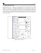
1600A-N1P Appendix D Drawings and Diagrams 1. 1600A-N1P Dimensional Overview 2. 1600A-N1P Unit Overview 3. 1600A-N1P Component Layout 4. 1600A-N1P Wiring Diagram 1600A-N1P Instruction Manual Rev. 0.
1600A-N1P Page intentionally blank Shipping Address: 3200 A-1 Research Forest Dr., The Woodlands Texas 77381 Mailing Address: P.O. Box 8067, The Woodlands Texas 77387-8067 Phone: 888.367.4286, 281.367.4100 • Fax: 281.292.2860 • www.detcon.com • sales@detcon.com 1600A-N1P Instruction Manual Rev. 0.
1600A-N1P Page intentionally blank Shipping Address: 3200 A-1 Research Forest Dr., The Woodlands Texas 77381 Mailing Address: P.O. Box 8067, The Woodlands Texas 77387-8067 Phone: 888.367.4286, 281.367.4100 • Fax: 281.292.2860 • www.detcon.com • sales@detcon.com 1600A-N1P Instruction Manual Rev. 0.
1600A-N1P Page intentionally blank Shipping Address: 3200 A-1 Research Forest Dr., The Woodlands Texas 77381 Mailing Address: P.O. Box 8067, The Woodlands Texas 77387-8067 Phone: 888.367.4286, 281.367.4100 • Fax: 281.292.2860 • www.detcon.com • sales@detcon.com 1600A-N1P Instruction Manual Rev. 0.
1600A-N1P Page intentionally blank Shipping Address: 3200 A-1 Research Forest Dr., The Woodlands Texas 77381 Mailing Address: P.O. Box 8067, The Woodlands Texas 77387-8067 Phone: 888.367.4286, 281.367.4100 • Fax: 281.292.2860 • www.detcon.com • sales@detcon.com 1600A-N1P Instruction Manual Rev. 0.
1600A-N1P Page intentionally blank Shipping Address: 3200 A-1 Research Forest Dr., The Woodlands Texas 77381 Mailing Address: P.O. Box 8067, The Woodlands Texas 77387-8067 Phone: 888.367.4286, 281.367.4100 • Fax: 281.292.2860 • www.detcon.com • sales@detcon.com 1600A-N1P Instruction Manual Rev. 0.