
User guide


1600A-N1P
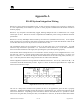
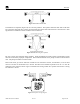
Figure 34 Recommended RS-485 communications set-up
Grounding
Another problem that can occur with RS-485 is incorrect grounding. Neither one of the two conductors in the
cable is ground. Both of the conductors are supplying a current to maintain a voltage level relative to an
external reference. A third conductor must be supplied to establish a reference through earth ground.
RS-485 is specified be able to work normally with a ±7V ground potential difference and survive ±25V surges.
In most applications, the equipment is powered from its own DC power supplies. This is good as long as the
supplies are located in the same physical location, and the DC commons are tied together and tied to earth
ground.
Problems occur when part of the data bus is powered by one supply and the second part of the bus is powered
by a power supply located elsewhere. In this case, earth ground is being relied upon to be the reference
between the two sections of the bus. If noise is induced onto the earth ground of one power supply and not the
other, data errors may occur. This is even more likely to occur when the distance between ground references
is large. A solution to this problem is to install an isolated repeater into the data bus to isolate the grounds
from each other, thus enabling the bus to use only one of the two references.
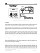
Isolated Repeaters
Repeaters can play many rolls in the implementation of an RS-485 data bus. Repeaters can: 1) Extend the
distance if needed to go further than 4000 feet. 2) Allow for the addition of more devices to the bus. 3)
Increase signal strength and integrity. 4) Solve grounding problems and solve some of the problems that occur
when an incorrect wiring scheme is implemented.
A repeater consists of two transceivers working together. One transceiver is connected to the main data bus
and the other transceiver connects to the remainder of the devices as it creates a new and separate data bus.
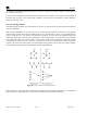
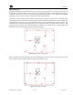
depicts a data bus that implements an undesirable branched wiring scheme. Depending on the
length of the taps of slave 1 and slave 2, they may or may not communicate properly back to the master. Long
lengths of cable to slaves 1 and 2 create four ends to the cable instead of two, which cannot be balanced with
the two terminating resistors on the extreme ends. Without a balanced bus, the long taps of slave 1 & 2 will
introduce reflections to the signal that can lead to problematic operation in the field. These problems can be
very hard to diagnose, isolate, and fix.
Figure 35
1600A-N1P Instruction Manual Rev. 0.1 Page 33 of 40