
Manual

1600A-N1R
1600A-N1R Instruction Manual Rev. 0.1 Page 8 of 38
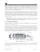
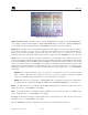
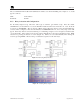
3.2 Connecting to the I/O Modules
4-20mA Gas Sensors
Connect 4-20mA type gas sensors to the Model DA4 4-20mA input modules. There are four 4-20mA inputs
in each Model DA4 module.
4-20mA
INPUT
COMM
M
S
D
L
S
D
Typical Sensors
Sensor 2
Sensor 1
Sensor 3
Sensor 4
Figure 9 Model DA-4 and 4-20mA Gas Sensors
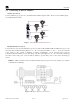
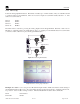
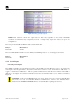
RS-485 Modbus Gas Sensors
Connect the five wires from the Modbus™ gas sensors (Detcon Model 600 and Model 700 Series types) to the
din rail mounted terminals labeled RS-485 “A”, “B”, and “Shld” and VDC “+” and “-”. Note: the controller
power supply is only capable of handling 3-3.5Amps accumulative. If the external sensors plus the
controller’s internal modules exceeds this rating, only three wires (RS-485 “A”, “B”, and “Shld”) should be
used and a remote DC power source should be utilized to provide DC power for the remote mounted gas
sensors.
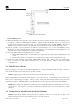
NOTE: A 120: end of line resistor should be installed on the last gas sensor in the serial loop to enhance
communications reliability.
Figure 10 Modbus™ Gas Sensor Connections