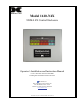
Model 1610-N4X NEMA 4X Control Enclosure Operator’s Installation and Instruction Manual Covers 1610-N4X and 1610-N4X-BBU In Fiberglass and Stainless Steel Enclosures DETCON, Inc. 4055 Technology Forest, Suite 100 The Woodlands, Texas 77381 Ph.281.367.4100 / Fax 281.298.2868 www.detcon.com December 14, 2011 • Document #2881 • Revision 1.
Model 1610-N4X This page left intentionally blank 1610-N4X Instruction Manual ii
Model 1610-N4X Table of Contents 1.0 1.1 1.2 1.3 1.4 2.0 2.1 2.2 Introduction.............................................................................................................................................. 1 Description ........................................................................................................................................... 1 Specifications .......................................................................................................................
Model 1610-N4X This page left intentionally blank Shipping Address: 4055 Technology Forest, Suite 100, The Woodlands Texas 77381 Mailing Address: P.O. Box 8067, The Woodlands Texas 77387-8067 Phone: 888.367.4286, 281.367.4100 • Fax: 281.292.2860 • www.detcon.com • sales@detcon.
Model 1610-N4X 1.0 Introduction Detcon Model 1610-N4X Gas Detection System consists of 3 major assemblies: 1. The 1610-N4X Fiberglass or Stainless Steel control enclosure. 2. The Model 10 single channel digital control modules. 3. The remote mount gas sensor assemblies.
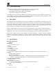
Model 1610-N4X 1.3 Auxiliary Alarm Relay Board (AARB) An Auxiliary Alarm Relay Board is included with each Detcon Model 1610-N4X. The board is mounted on the bottom quadrant of the motherboard. The AARB (Figure 1) consists of four interposing relays (contacts are rated 10Amp @ 120 VAC and 8Amp @ 30 VDC) with 24VDC coils. The AARB can be configured for Form-C dry contacts (common, normally open and normally closed), AC power, or DC power. 3.04 2.50 2.85 Ø0.165 X4 3.
Model 1610-N4X NOTE: If the Battery Option is installed (1610-N4X-BBU), the batteries are connected to P15 (VDC IN). Do not use the DC output of “ALM POWER” (P18-1 and P18-2). The Batteries are not designed to provide power for alarm devices. Mounting hardware is provided on the 1610-N4X motherboard for two additional Auxiliary Alarm Relay Boards. 1.4 Remote Alarm Reset A remote mounted normally open momentary switch may be used to reset the alarms of all Model 10 controllers.
Model 1610-N4X www.detcon.
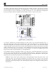
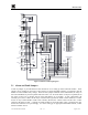
Model 1610-N4X BRKR 1 2 P11 + - PS DC D2 6A 50V 1 2 D1 6A 50V P12 PS VAC GND 1 N 2 L1 3 P13 ALM RESET 1 2 A1 A2 A3 A4 A5 A6 A7 A8 A9 A10 A11 A12 A13 A14 A15 A16 P14 VDC IN + - 1 2 P15 VAC IN L1 N GND 1 2 3 P16 RS-485 B(-) Shld P17 ALM POWER P18 + - L1 P19 N GND CH1 1 2 3 1 2 3 4 5 RS-485 Shield to Gnd Tie to Chassis + mA NC NO COM NC NO COM NC NO COM 4-20 OUT P20 Earth Ground FAULT 1 2 ALM 1 ALM COIL + - AL1-NO AL1-NC Al1-COM -485-A RST 485-S 485-B -XMXMXM-VDCVDCVDC-
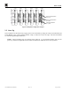
4-20 OUT FAULT ALM 1 ALM2 SENSOR Model 1610-N4X + mA NC NO C NC NO C NC NO C + - CH1 CH2 CH... 1 2 3 4 5 6 7 9 9 10 11 12 13 14 1 2 3 4 5 6 7 9 9 10 11 12 13 14 1 2 3 4 5 6 7 9 9 10 11 12 13 14 A B C D E F G H I JP1 A B C D E F G H I JP2 CH14 A B C D E F G H I JP... 1 2 3 4 5 6 7 9 9 10 11 12 13 14 A B C D E F G H I JP14 CH15 CH16 1 2 3 4 5 6 7 9 9 10 11 12 13 14 1 2 3 4 5 6 7 9 9 10 11 12 13 14 A B C D E F G H I JP15 Alarm 2 Jumper positions A, B, anc C.
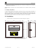
Model 1610-N4X 3.0 Maintenance & Repair The Detcon Model 1610-N4X’s modular design allows for minimum ‘down-time’ during maintenance and/or repair. Model 10 Control Modules A Model 10 control module may be changed by simply loosening its mounting screw and sliding the module out of its card cage. See the Model 10 Instruction Manual for more information on the Model 10 controllers.
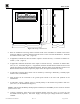
Model 1610-N4X Power Supply Replacement of the power supply is accomplished by, removing the 10 screws that secure the 1610-N4X face plate, disconnecting all wiring to/from the power supply, and removing the three screws holding the power supply bracket to the Motherboard. Remove the four screws that hold the power supply bracket to the power supply and reassembly with the new power supply.
Model 1610-N4X 6.0 Revision Log Revision Date 1.2 03/21/2007 1.3 07/21/2011 1.4 12/14/11 1610-N4X Instruction Manual Changes made Previous Release Added revision log. Removed references to Common alarm in drawings and text. Fixed error in wiring diagram. Update to include SS Enclosure Rev. 1.
Model 1610-N4X This page left intentionally blank 1610-N4X Instruction Manual Rev. 1.
Model 1610-N4X This page left intentionally blank 1610-N4X Instruction Manual Rev. 1.
Model 1610-N4X This page left intentionally blank 1610-N4X Instruction Manual Rev. 1.
Model 1610-N4X This page left intentionally blank 1610-N4X Instruction Manual Rev. 1.
Model 1610-N4X This page left intentionally blank 1610-N4X Instruction Manual Rev. 1.
Model 1610-N4X This page left intentionally blank 1610-N4X Instruction Manual Rev. 1.
Model 1610-N4X This page left intentionally blank 1610-N4X Instruction Manual Rev. 1.
Model 1610-N4X This page left intentionally blank 1610-N4X Instruction Manual Rev. 1.