SmartWireless® CX Sensor Station for SmartWireless® Mobile Gas Detection System Operator’s Installation and Instruction Manual DETCON, Inc. 4055 Technology Forest Blvd., The Woodlands, Texas 77381 Ph.713.559.9200 / Fax 281.298.2868 www.detcon.com Nov. 20, 2013 • Document #4409 • Revision 1.
Sentinel CX This page left intentionally blank Shipping Address: 4055 Technology Forest Blvd., The Woodlands Texas 77381 Mailing Address: P.O. Box 8067, The Woodlands Texas 77387-8067 Phone: 713.559.9200 • Fax: 281.292.2860 • www.detcon.com • sales@detcon.com Sentinel CX Sensor Station IM Rev. 1.
Sentinel CX Table of Contents 1. Introduction............................................................................................................................................1 1.1 1.2 1.3 1.4 1.5 1.6 1.7 1.8 1.9 2. 3. Safety Guidelines for safe use ...............................................................................................................9 Installation...........................................................................................................................
Sentinel CX This page left intentionally blank Shipping Address: 4055 Technology Forest Blvd., The Woodlands Texas 77381 Mailing Address: P.O. Box 8067, The Woodlands Texas 77387-8067 Phone: 713.559.9200 • Fax: 281.292.2860 • www.detcon.com • sales@detcon.com Sentinel CX Sensor Station IM Rev. 1.
Sentinel CX 1. Introduction 1.1 Features The SmartWireless® CX Sensor Station (Figure 1) is an accessory to the SmartWireless® CXT. The CX wirelessly transmits the data from the sensors to the CXT and includes a battery that powers the radio, alarm devices, and the attached sensors. The CX can sustain either two or four 4-20mA wired sensors. Remote mounted gas detection sensors include any analog 4-20maDC device such as; toxic gas, combustible gas, or oxygen deficiency sensors.
Sentinel CX SmartWireless® CXT Controller The Detcon SmartWireless® CXT controller is a multi-channel mobile gas detection control system mounted on a tripod or a suitable stand. The CXT can be utilized as a self-contained gas detection, display/alarm system package or wirelessly connected to the main network. The CXT is equipped with an auto configure system to automatically search for Detcon equipment associated with the controller.
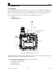
Sentinel CX 1.4 Power Supply-Internal Rechargeable Battery and Charging Accessory SmartWireless® CXT is powered by an internal rechargeable Smart Battery capable of delivering continuous operation in a no alarm condition for two to eight weeks depending on the quantity and type of sensors tied to the control panel. The internal re-chargeable battery pack shall only be charged in a nonhazardous area where the required operating temperature limits are 0C to +45C.
Sentinel CX routes around congestion and line-of-sight obstacles while improving throughput as subscriber device density increases. The radio module is housed in a black ABS box mounted inside of the CX stainless steel enclosure. The standard package includes two PCAs mounted inside the black ABS box (radio PCA and Smart battery charging PCA), 5 dB antenna, and a protective antenna cover.
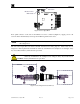
Sentinel CX Modbus Address LSD Switch Modbus Address MSD Switch Figure 3 Sensor Input PCA Four "quick connects" on the side of the CXT are for sensor connection (Figure 4), supply power to the sensor from the internal battery and accept the 4-20mA signal from the sensor. NOTE Power supplied to the sensors is 11VDC. Any attached sensor must be designed to work at this voltage level. The four sensor input lines are fused at the PC board level for safety purposes.
Sentinel CX 1.7 Alarm Outputs The SmartWireless® CXT can optionally include an internal Relay PCA for activating alarm annunciators. The Relay PCA includes four Class I Division II relays rated for 10A @ 30VDC/250VAC. If the SmartWireless® CXT includes an attached strobe and/or horn, these devices are also activated by the Relay PCA. Each Relay PCA must have a unique Modbus address. The Relay PCA includes a single rotary switch to set its Modbus address (Figure 5).
Sentinel CX Sensor Connector Ratings Voltage: 9-11.2 VDC Current: 2 Amps max through single relay connector (2 Amps max total across 4 connectors. When utilizing ‘Wet’ contacts, the maximum power that can be drawn by the annunciators is 2A. CAUTION The Smart Wireless® CXT is also available with ‘Dry’ relay contacts (Figure 7).
Sentinel CX Detcon Approved Battery Charger Accessory Ratings: AC Input Power Voltage: 100-240 VAC, 50-60 Hz (requires correctly selected 110 VAC or 220 VAC Charger) Current: 2.0 Amps maximum DC Output Power Voltage: 24+/- 1 VDC Current: 3.1 Amps maximum The SmartWireless® CXT must be charged with the Detcon supplied Battery Charger. (Detcon P/N: 976-0003BC-00T for 110VAC and P/N 976-0003BC-220 CAUTION for 220VAC ). Use of any other charger may damage the controller.
Sentinel CX 2. Safety Guidelines for safe use If equipment is used in a manner not specified by Detcon, the protection provided by the equipment may be impaired. It is mandatory to read and follow all of the Safety Warnings and Cautions listed below. Warning This apparatus is suitable for use in Class (as applicable), Division 2 groups (as applicable), or unclassifiedlocations. Warning Explosion Hazard.
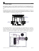
Sentinel CX 3. Installation 3.1 Initial Setup NOTE The Detcon tripod (P/N 975-TRIPOD-100) provides a stable and mobile base for the SmartWireless® CX Sensor Station. A maximum of two sensors can be secured to the tripod using Detcon brackets (P/N 943-004413-000) installed on the tripod 1. Unpack the tripod, open the legs and place on a level surface. 2. Mount the CX to the center pipe using the supplied U-bolts in accordance with Figure 9.
Sentinel CX Tripod Leg Mounting Hardware Sensor with Mini Condulet Mounting Plate Mounting Support Figure 10 Attach Sensor Brackets to Tripod 6. Hang the sensors on the brackets using the hook and pin supplied with the bracket. 7. Connect sensor cables to the sensor ports on the CX (Figure 1). 8. If the unit is ordered with the optional external A1 C1D2 Horn, the horn should be mounted either on the tripod, or on a separate tripod. .
Sentinel CX White Gray Black Turck Alarm Cable from Sentinel Green/Yellow Red Black To Horn C1D1 Cable Assembly 12-24 Alarm Terminal PCA Figure 11 A1 C1D2 Alarm Connections Battery Installation 9. Loosen the screws holding the door panel in place, and swing the front door of the enclosure open to gain access to the battery bracket. Figure 12 Enclosure Sentinel CX Sensor Station IM Rev. 1.
Sentinel CX 10. Unplug the connector from the transceiver, and move it out of the way to gain access to the screws holding the battery bracket in place. There should be enough of a service loop to safely move this connector out of the way for removal/installation of the battery bracket. Figure 13 Connector to Transceiver 11. Remove the 6-32 screws and washers holding the battery bracket is place, and remove the bracket from the enclosure.
Sentinel CX 12. Install the battery pack in the bracket. The battery will fit snugly into the holder, being somewhat held in place by the foam padding in the bracket. Figure 15 Battery and Battery Bracket 13. Position the battery bracket (and battery) with the connector on the left side, and install the battery and bracket in the enclosure using the 6-32 screws removed is step 11.
Sentinel CX 16. Cycle power to ensure that the unit powers up. The LED on the top of the unit should illuminate to indicate power is applied. Close the front door panel and screw the front cover down. The screws should be tightened down to a ‘snug’ fit. These screws do not need to be tightened down completely, but need to be tightened down enough to give the front door a water tight seal. 17.
Sentinel CX 4. Recharging the Internal Battery Pack 4.1 Non-Hazardous Area Location At a safe time interval prior to full discharge of the internal battery pack, relocate the CXT Controller to a non-hazardous area that has suitable 110 VAC or 220 VAC AC power receptacles available. 4.
Sentinel CX 5. Troubleshooting Guide Sensor COMM Error Verify all SmartWireless CX devices have a unique Modbus ID number. Verify the Sensor Input PCA and Relay PCA Modbus address are set correctly Verify the Radio Module Modbus address is set correctly Sensor Fault Verify if sensor displays any fault. If so, follow sensor trouble shooting notes. Verify if sensor cell needs replacement.
Sentinel CX 6. Customer Support and Service Policy Detcon Headquarters Shipping Address: 4055 Technology Forest Blvd, The Woodlands, Texas 77381 Mailing Address: P.O. Box 8067, The Woodlands Texas 77387-8067 Phone: 713.559.9200 Fax: 281.298.2868 • www.detcon.com • service@detcon.com • sales@detcon.com All Technical Service and Repair activities should be handled by the Detcon Service Department via phone, fax or email (contact information given above).
Sentinel CX 7. Warranty Notice Detcon Inc. warrants the SmartWireless® CX System to be free from defects in workmanship of material under normal use and service for one year from the date of shipment. Detcon Inc. will repair or replace without charge any such equipment found to be defective during the warranty period. Full determination of the nature of, and responsibility for, defective or damaged equipment will be made by Detcon Inc. personnel.
Sentinel CX 8. Appendix 8.
Sentinel CX 8.
Sentinel CX 8.3 Revision Log Revision Date 1.0 1.1 1.2 03/27/2013 10/30/13 11/20/13 Changes made Release Update for removable battery pack Updates for Approval Agency Approval LBU LBU BM Shipping Address: 4055 Technology Forest Blvd., The Woodlands Texas 77381 Mailing Address: P.O. Box 8067, The Woodlands Texas 77387-8067 Phone: 713.559.9200 • Fax: 281.292.2860 • www.detcon.com • sales@detcon.com Sentinel CX Sensor Station IM Rev. 1.