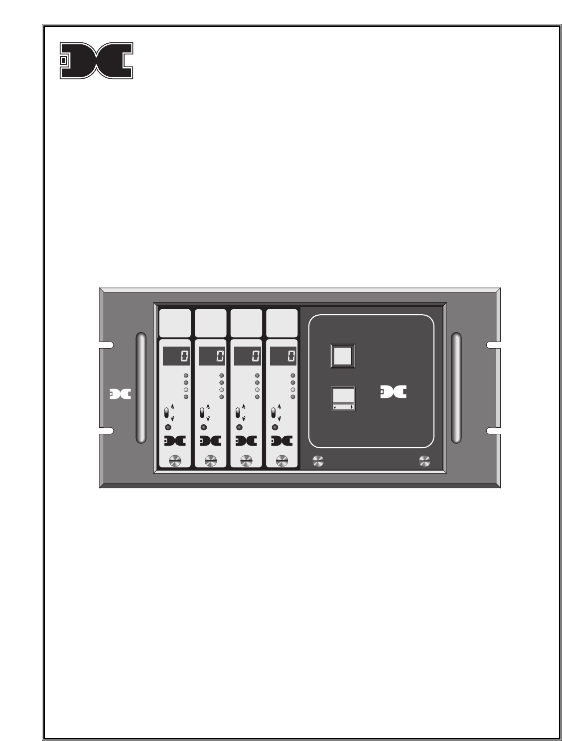
Detcon detcon inc. Model 412B Rack Mount Control Enclosure MODEL 12B MODEL 12B MODEL 12B HYDROGEN SULFIDE HYDROGEN SULFIDE HYDROGEN SULFIDE MODEL 12B HYDROGEN SULFIDE MONITOR ppm H2S MONITOR ppm H2S MONITOR ppm H2S MONITOR ppm H2S POWER ON/OFF Model PS80-12B Model 412B ALARM 3 ALARM 3 ALARM 3 ALARM 3 ALARM 2 ALARM 2 ALARM 2 ALARM 2 ALARM 1 ALARM 1 ALARM 1 ALARM 1 FAULT FAULT FAULT FAULT able able able able ALARM ALARM ALARM ALARM FUSE detcon inc.
Table of Contents 1.0 1.1 1.2 1.3 1.4 1.5 1.6 1.7 1.8 Introduction Description Specifications Schematics Installation Start-up Maintenance & Repair Spare Parts List Warranty 1.0 INTRODUCTION Detcon Model 412B consists of 3 major assemblies: 1. The NEMA 1 rack mount control enclosure. 2. The single channel digital control modules. 3. The remote mount gas sensor assemblies. The NEMA 1 control enclosure is detailed in section 1.0 of the manual, the control modules in section, 2.
Outputs Discrete Analog 4-20 mA DC Serial RS-485 Modbus™ Alarm Relays (discrete or zoned) Contacts include common with jumper selectable choice (on controller) of normally-open or normally-closed for four alarms Resistive load: 5A, 250 VAC; 5A, 30 VDC Inductive load: 2A, 250 VAC; 2A, 30 VDC Max. operating current: 5A Operating Temperature Range -40°F to +175°F Warranty One year 1.3 SCHEMATICS Typ.
PS80-12B Power Supply Schematic/Wiring Diagram Power Supply VAC In Power Supply Power Supply DC Out TB1 TB2 16ga x 6" BLK Pin 5 Com Pin 7 + 16ga x 6" RED 16ga x 6" Pin 1 Pin 2 N Pin 3 L GND - GRN N - WHT L1 - BLK 16ga x 6" 16ga x 6" P2 P1 Power Switch BLK 16ga x 9" BLK 16ga x 9" TAN 22ga x 9" TAN 22ga x 9" RED 16ga x 9" RED 16ga x 9" D1 6A 50V D2 6A 50V P5 P3 Fuse L1 In N In GND In +DC In –DC In +DC Out –DC Out BLK 16ga x 9" BLK 16ga x 9" P4 1.4 INSTALLATION 1.
Figure 1 Panel cutout (centered) 12.5 x 6.65 Panel depth - 8.75 7 .375 3 .218 Slot Detail use 10-32 screw 14 7. Based on the application and use of relay contact outputs, complete all wiring terminations prior to application of power. Shut-in controls may be omitted until system test is complete. Terminals are labeled “ALARM 1”, “ALARM 2”, “ALARM 3”, and “FAULT” (COM & NO/NC). Relay contact outputs may be discreet or zoned via the gold-plated jumper tabs. 8.
1.5 START UP Upon completion of all field wiring: Depress the power switch located on the front panel. Note that each Model 12B controller digital display illuminates. Varying readings may occur during sensor warm-up. A 10 second alarm delay will occur on power up. Refer to section 3.0 for additional sensor start-up detail. 1.6 MAINTENANCE & REPAIR The Detcon Model 412B’s modular design allows for minimum down time during maintenance and/or repair.