
Manual


1.4 INSTALLATION
1. Securely mount the 412B enclosure in accordance with the drawing in figure 1.
NNoottee::
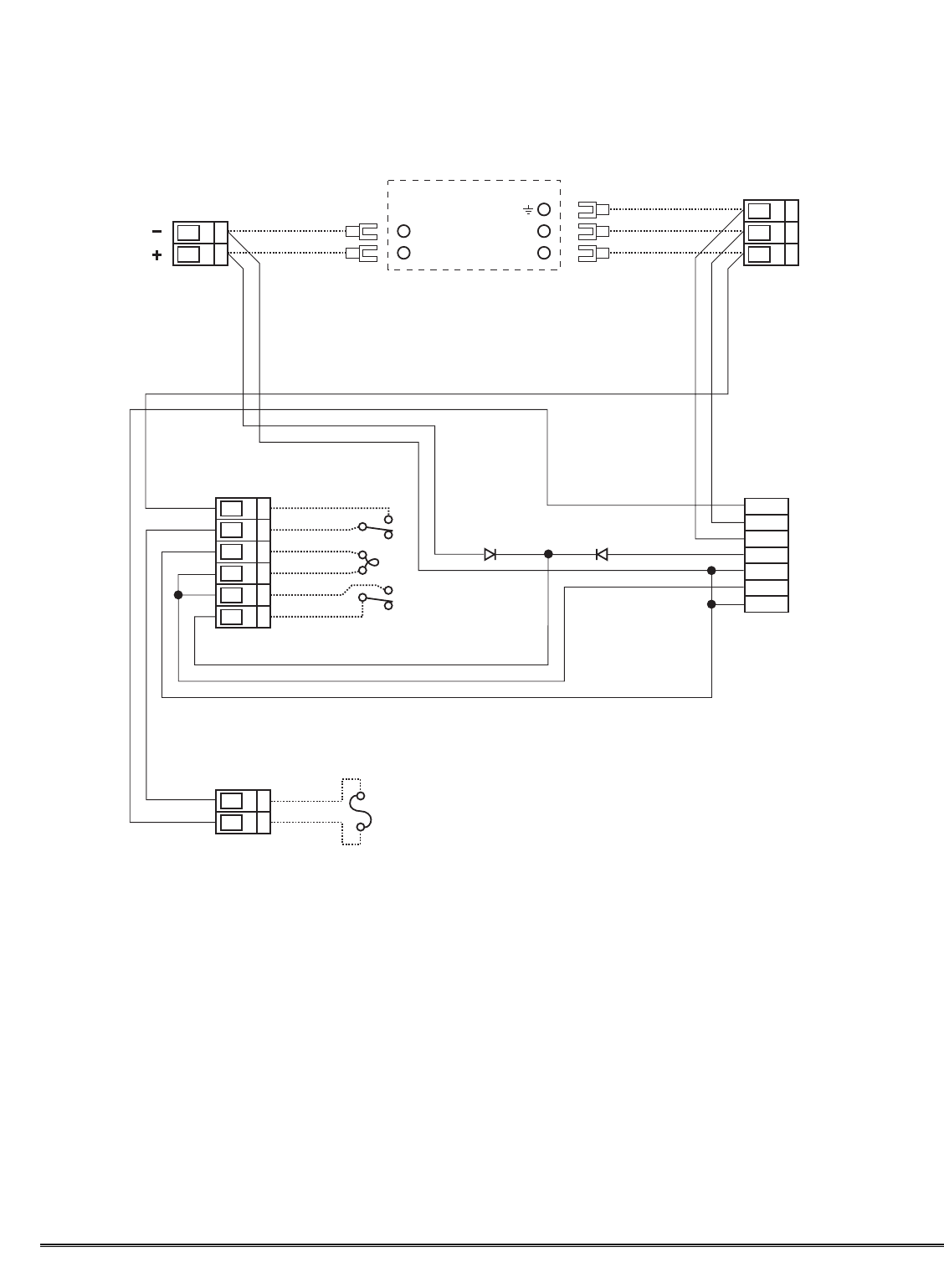
Reference figure 2 for wiring terminations.
2. Connect 117VAC input to the terminal strip labeled “VAC IN” (L1, N, GND).
3. If applicable, connect a 24VDC source or standby battery to the terminal strip labeled “VDC IN” (+ and
–
).
4. Refer to installation and wiring detail of remote mount sensor assemblies as detailed in section 3.0. Terminate
field wiring from sensors to the 412B motherboard. Terminals are labeled “SENSOR” (MA, + and —).
5. If applicable, terminate the discrete 4-20 mA outputs to external device(s). Terminals are labeled “4-20 mA OUT”
(+ and —).
6. If applicable, terminate the RS-485 serial output to external device(s). Terminals are labeled “RS-485” (A+, B–,
and Shield).
Model 412B Rack Mount Control Enclosure PG.4
L1 In
Fuse
L1 - BLK
N - WHT
GND - GRN
BLK
16ga x 9"
BLK 16ga x 9"
Power
Switch
RED 16ga x 9"
RED 16ga x 9"
TAN 22ga x 9"
TAN 22ga x 9"
BLK 16ga x 9"
BLK 16ga x 9"
D2 6A 50V
RED
BLK
Power Supply
Pin 5 Com
Pin 7 +
Pin 2 N
Pin 3 L
16ga x 6"
P1
TB1
TB2
N In
GND In
+DC In
–DC In
+DC Out
–DC Out
Pin 1
16ga x 6"
16ga x 6"
16ga x 6"
16ga x 6"
P2
P3
P4
P5
D1 6A 50V
Power
Supply
DC Out
Power
Supply
VAC In
PS80-12B Power Supply Schematic/Wiring Diagram