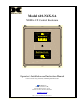
Model 610-N4X-SA NEMA 4 X Control Enclosure Model 610-N4X www.detcon.com detcon Inc. RESET/ACK BUTTON Detcon Inc. Gas Detection Control System www.detcon.com Houston Texas Operator’s Installation and Instruction Manual Covers 3 and 5 relay, Stainless and Fiberglass Enclosures DETCON, Inc. 3200 Research Forest Dr., The Woodlands, Texas 77387 Ph.281.367.4100 / Fax 281.298.2868 www.detcon.com July 15, 2005• Document #3001• Revision 0.
Model 610-N4X-SA This page left intentionally blank 610-N4X-SA Instruction Manual ii
Model 610-N4X-SA Table of Contents 1.0 1.1 1.2 1.3 1.4 2.0 2.1 Introduction.............................................................................................................................................. 1 Description ........................................................................................................................................... 1 Specifications .........................................................................................................................
Model 610-N4X-SA This page left intentionally blank Shipping Address: 3200 A-1 Research Forest Dr., The Woodlands Texas 77381 Mailing Address: P.O. Box 8067, The Woodlands Texas 77387-8067 Phone: 888.367.4286, 281.367.4100 • Fax: 281.292.2860 • www.detcon.com • sales@detcon.
Model 610-N4X-SA 1.0 Introduction Detcon Model 610-N4X-SA Gas Detection System consists of 3 major assemblies: 1. The 610-N4X-SA Fiberglass or Stainless Steel control enclosure. 2. The Model 10 single channel digital control modules. 3. The remote mount gas sensor assemblies.
Model 610-N4X-SA Inductive load: 5A, 240 VAC; 7.5A, 30 VDC Max. operating current: 10A Time delay relays K2 (and if applicable K5) Resistive load: 10A, 240 VAC; 10A, 30 VDC Inductive load: 7A, 240 VAC; 7.5A, 30 VDC Max. operating current: 10A Operating Temperature Range -40°C to +175°C Battery Backup (If applicable) 2ea. 12V 2.9Ah batteries in series; ½ hour minimum operating time Warranty One year 1.
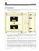
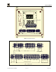
Model 610-N4X-SA the latching position and alarm conditions have passed. Each Model 10 controller also has its own discrete alarm reset switch, which is discussed further in the Model 10 Instruction Manual. 2.0 Installation 1. Securely mount the 610-N4X-SA Enclosure in accordance with figure 1. Stainless Steel version mounting footprint is the same as that shown. 25.59in [649.94mm] 10.4in [263.91mm] 22.75in [577.85mm] Model 610-N4X www.detcon.com detcon Inc.
Model 610-N4X-SA terminations should be completed prior to application of power. Shut-in controls may be omitted until system test is complete. PS VAC L1-BLK N-WHT GND-GRN RED + BLK - + - L1 N GND A(+) B(-) Shld CH1 + - Alarm 2 Alarm 1 Fault VDC- ALM2 ALM1 FAULT + mA NC NO COM NC NO COM NO NC COM + - Out VDC + L1 N GND Sensor VAC VDC Typ.
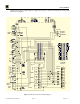
Model 610-N4X-SA 610 - Mother Board A1 BRKR + - P1 PS VAC L1 N P3 GND + - P2 PS DC Battery Backup MODEL 10 MODEL 10 MODEL 10 MODEL 10 MODEL 10 MODEL 10 ALM 2 ALM 1 FAULT ALM 2 ALM 1 FAULT ALM 2 ALM 1 FAULT ALM 2 ALM 1 FAULT ALM 2 ALM 1 FAULT ALM 2 ALM 1 FAULT ALARM RESET ALARM RESET TEST SENSOR 7 2 ALM2 + mA NC NO C NC NO C NC NO C + - 4-20 FAULT ALM 1 VAC IN L1 N P7 GND RS-485 A(+) B(-) P7 Shld ALM POWER Low Voltage Cut-Off TB3 TB2 P5 OUT P4 VDC IN ALARM RESET TEST CH1
Model 610-N4X-SA 6. Each alarm has an associated set of dry contacts from the Alarm/Fault relay’s (Figure 3 and Figure 5). These dry contact terminals consist of a Common relay connection through a terminal disconnect, and the NC and NO Contacts via through terminals (Figure 4). Disconnect Terminal Block 24 25 26 COM - Common NC - Normally Closed NO - Normally Open COM NC NO Through Terminal Block Figure 5 Typical Dry Contact Connections 7.
Model 610-N4X-SA Adding/Removing Control Modules When adding or removing Control Modules it is imperative that the backplane jumpers are correctly removed or added to insure proper operation of the fault alarm circuitry (see Figure 7). When removing a Control Module, the jumpers for Fault (JPx-G, H, and I) directly to the left of the module being removed, must be installed to allow proper signal flow and fault operation.
Model 610-N4X-SA 4.0 Spare Parts List Part # Description 363-752400-000 0224 305-300410-000 0302 3309 330-901100-024 330-794500-124 226-910120 500-505000-000 3423-2 110 watt, 24 VDC switcher power supply Gold plated jumper tab Din-Rail Mounted Fused Terminal 5Amp 3AG Slow-Blo Fuse DPDT 8 Pin Octal 10A Relay DPDT Hermetically Sealed 8 Pin Octal 10A Relay DPDT 8 Pin Octal Timer Relay 20 Amp Circuit Breaker Low Voltage Cut-off PCB (If applicable) 12V 2.9Ah Battery (If applicable) 5.0 Warranty Detcon Inc.