
Manual
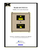

Model 610-N4X-SA
Table of Contents
1.0 Introduction.............................................................................................................................................. 1
1.1 Description ........................................................................................................................................... 1
1.2 Specifications ....................................................................................................................................... 1
1.3 Relay Logic Description....................................................................................................................... 2
1.4 Front Panel Alarm Reset ...................................................................................................................... 2
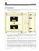
2.0 Installation................................................................................................................................................ 3
2.1 Start Up ................................................................................................................................................ 6
3.0 Maintenance & Repair ............................................................................................................................ 6
4.0 Spare Parts List........................................................................................................................................ 8
5.0 Warranty .................................................................................................................................................. 8
Table of Figures
Figure 1 Mounting................................................................................................................................................ 3
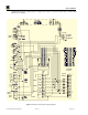
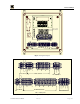
Figure 2 Motherboard Schematic Wiring Diagram.............................................................................................. 4
Figure 3 Component Layout................................................................................................................................. 5
Figure 4 Alarm Wiring......................................................................................................................................... 5
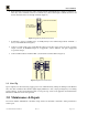
Figure 5 Typical Dry Contact Connections.......................................................................................................... 6
Figure 6 Input Power Connections....................................................................................................................... 6
Figure 7 Backplane Configuration Jumpers......................................................................................................... 7
610-N4X-SA Instruction Manual iii