INSTRUCTION MANUAL Model 700 Series Remote Sensor/Alarm Relay Module With Profibus DP Interface DETCON, Inc. 3200 Research Forest Dr., The Woodlands, Texas 77387 Ph.281.367.4100 / Fax 281.298.2868 www.detcon.com November 20, 2009• Document #3225• Revision 0.
700 Profi-RAM This page left intentionally blank Shipping Address: 3200 A-1 Research Forest Dr., The Woodlands Texas 77381 Mailing Address: P.O. Box 8067, The Woodlands Texas 77387-8067 Phone: 888.367.4286, 281.367.4100 • Fax: 281.292.2860 • www.detcon.com • sales@detcon.com 700 Profi-RAM 0.
700 Profi-RAM Table of Contents 1. 2. 3. 4. 5. 6. Introduction ................................................................................................................................................1 1.1 Description.......................................................................................................................................... 1 1.2 Installation ..............................................................................................................................
700 Profi-RAM This page left intentionally blank Shipping Address: 3200 A-1 Research Forest Dr., The Woodlands Texas 77381 Mailing Address: P.O. Box 8067, The Woodlands Texas 77387-8067 Phone: 888.367.4286, 281.367.4100 • Fax: 281.292.2860 • www.detcon.com • sales@detcon.com 700 Profi-RAM 0.
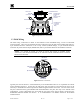
700 Profi-RAM 1. Introduction 1.1 Description The Model 700 Remote Sensor/Alarm Relay Module with Profibus Interface (known as the Profibus Remote Alarm Module or Profi-RAM) is sold separately as an accessory for Model 700 Series Gas Sensors. It is a universal design and can be used with any of the Model 700 Gas Sensors. The Profi-RAM is provided in an explosion-proof junction box constructed of either epoxy-painted aluminum or 316 stainless steel.
700 Profi-RAM 5.5" 4.95" 3.675" Mounting Bolt Wall (or other mounting surface) Ø0.2650 X2 Mounting Holes Model 700 5.25" Explosion Proof Enclosure Junction-Box Three - 34"NPT Fittings Figure 2 Profi-RAM Mounting 5.5" 4.95" 3.675" 5.25" Wall (or other Explosion Proof Enclosure Junction-Box (Detcon's Junction-Box shown) 12.25" Use Spacers to move the J-Box and Sensor Assembly away from the wall at least 0.25-0.5" to allow access to Sensor detcon inc. 5.195" detcon inc. MODEL TP-700 7.
00 Profi-RAM Interconnect Wiring Connectors Profi-RAM Electronics Package The Electronics Package sets on the stand-offs in the enclosure External Wiring 6" Provide at least a 6" Service Loop for all wiring Input Port Input Port Figure 4 Exploded View of Assembly 1.3 Field Wiring The field wiring connections are made on the backside of the Profi-RAM using a series of removable connector blocks.
700 Profi-RAM NOTE: If the 700 sensor and Profi-RAM are directly connected, it is not necessary to install/use the transient protection module that is shipped with every 700 Gas Sensor. Fault Annunciator Power Input mA Output Model 700 Alarm 1 Annunciator Profibus Interface Alarm 2 Annunciator detcon inc. detcon inc. MODEL XX-700 PGM1 PGM2 ZERO SPAN Sensor Figure 6 Installation with 700 Gas Sensor If remote sensor separation is required, the Profi-RAM will be separated from the 700 sensor.
700 Profi-RAM NOTE 3: The same recommended cables should be used for the connection between the master control device and the Profi-RAM. However, if only the 4-20 mA signal is being used by the master/host controller then only the 3 wire cable is required. 2. Operator Interface The operator interface of the Profi-RAM is very similar to the Model 700 Gas Sensor. It uses the identical LED display, same programming magnet, and has the same magnetic programming switches (PGM1/ZERO and PGM2/SPAN).
700 Profi-RAM NOTE: For any other required operational changes, the 700 Gas Sensor must be accessed directly.
700 Profi-RAM In normal operation, the 4-20 mA current output from the Profi-RAM corresponds with the present gas concentration and full-scale range. The Profibus serial output provides the current gas reading and fault status on a continuous basis when polled. If the Modbus™ communication between the Profi-RAM and the 700 Gas Sensor is not functioning, the ProfiRAM will display “COMM” and the ‘FLT’ LED will be illuminated.
700 Profi-RAM mA Output Item appears as: “mA Output XX.XX” Input Voltage Supply Item appears as: “Voltage XX.XXVDC” Sensor Temperature Item appears as: “Temp XXC” Alarm 1 Settings Items appear as: “Alarm1 Level = X.X” “Alarm1 Ascending / Descending” “Alarm1 Latching / Non-latching” “Alarm1 Energized / Non-energized” Alarm 2 Settings Items appear as: “Alarm2 Level = X.
700 Profi-RAM The user can then choose to either: 1) move to another menu item by executing a momentary hold, or 2) return to Normal Operation via 5 second automatic timeout. 3.3 Set Serial ID The Profi-RAM can be polled serially via the Profibus. The Profi-RAM Serial ID # should be set as a slave device to a master polling device. NOTE: The Serial ID of the Model 700 Gas Sensor connected to the Profi-RAM must be set to ID = 01 for proper communication between the two devices.
700 Profi-RAM The display will scroll “Set Ascending” and show “Yes” or “No”. Momentarily swipe PGM1 to select the desired choice (yes = ascending and no = descending). Hold the magnet over PGM1 until the LCD scrolls, “Saved” (about 3 seconds). The display will scroll “Set Latching” and then show “Yes” or “No”. Use a swipe of PGM1 to select choice (yes = latching and no = non-latching). Hold the magnet over PGM1 until the LCD scrolls, “Saved” (about 3 seconds).
700 Profi-RAM 3.6 PDP Diagnostics PDP Diagnostics displays the current status of the AnyBus Profibus connection to the network. This information is useful for verifying the connection properties and status between the ProfiRam and the AnyBus IC and, also between the AnyBus IC and the Profibus network. From the PDP Diagnostics text scroll, hold the magnet over PGM2 until the “V” prompt appears and then hold continuously for an additional 3 seconds.
700 Profi-RAM The PROFIBUS-DP Protocol is implemented using the HMS Industrial Networks, Inc. AnyBus-IC for PROFIBUS. The Profibus National Organization (PNO) Identifier for this IC is 0x1810. The AnyBus-IC GSD file and bitmaps must be downloaded from the HMS Industrial Networks, Inc website at http://www.anybus.com. The GSD file is used to configure the Profibus Master to recognize the Profi-RAM. The Profi-RAM implements the following function of the AnyBus IC: INPUT: 16 Byte (8 word).
700 Profi-RAM Word 7: Sensor Temperature. Minimum value: -40 Maximum value: 75 Word 8: Range Divisor. This setting is determined by which sensor is connected to the ProfiRAM. For a FP-700 or TP-700, this setting will be 1. For an IR-700, the gas reading will be divided by this number. For a DM-700: • If range is 0-9, setting is 2 decimal places (divide by 100); • If range is 10-25, setting is 1 decimal place (divide by 10); • If range is 26+, setting is 0 (no decimal places). 5.
700 Profi-RAM Enclosure Classification Nema 7 and Nema 4X 6.2 Spare Parts Part Number 927-70000P-000 8522-750 960-202200-000 Spare Parts ProfiBus-RAM Electronics Module ¾” NPT Plug Condensation Prevention Packet 6.3 Revision Log Revision Date 0.2 08/13/2009 0.03 11/20/2009 Changes made Specifications: Corrected lower operating temperature. Revised information on relay contact rating to match CSA/UL labeling. Added revision log Description of Word 8: Range Divisor.