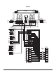
Detcon detcon inc. Model 812-N4X NEMA 4 Control Enclosure POWER ON/OFF FUSE 2 AMP ALARM DISABLE Model 812-N4X FUSE detcon inc.
Table of Contents 1.0 Introduction 1.1 Description 1.2 Specifications 1.3 Multiple Alarm Relay Circuit 1.4 Alarm Disable 1.5 Remote Alarm Reset 1.6 Installation 1.7 Start-up 1.8 Maintenance & Repair 1.9 Spare Parts List 1.10 Warranty 1.0 INTRODUCTION Detcon Model 812-N4X consists of 3 major assemblies: 1. The NEMA 4 fiberglass control enclosure. 2. The Model 12B single channel digital control modules. 3. The remote mount gas sensor assemblies. The NEMA 4 control enclosure is detailed in section 1.
1.2 SPECIFICATIONS Electrical Classification NEMA 4X Dimensions 15.75''W x 18''H x 9.75''D Capacity 8 single channels Power Input 85-264VAC/24VDC Power Consumption 5 watts per channel (full alarm peak load) Outputs Discrete Analog 4-20 mA DC Serial RS-485 Modbus™ Discrete or zoned alarm relays Contacts include common with jumper selectable choice (on controller) of normally-open or normally-closed for four alarms Resistive load: 5A, 250 VAC; 5A, 30 VDC Inductive load: 2A, 250 VAC; 2A, 30 VDC Max.
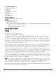
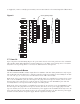
Figure 1 Multiple Alarm Relay Circuit I/O J1 J2 F1 J3 F2 J4 F3 C F4 NC 4 NO 4 C 3 NC 3 2 NO 1 C NC 2 NO C NC 1 NO I/O Jumpers #4 #3 #2 #1 5 Amp Micro Fuse In/Out Com NC NO Com NC NO Com NC NO Com NC NO #4 Coil #4 Coil #3 Coil #2 Coil #1 Common #3 #2 #1 Model 812-N4X NEMA 4 Control Enclosure PG.
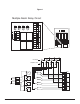
Figure 2 TB1 Pin 3 L TB2 P1 16ga x 6" 16ga x 6" 16ga x 6" BLK 16ga x 9" BLK 16ga x 9" TAN 22ga x 9" TAN 22ga x 9" RED 16ga x 9" RED 16ga x 9" P3 Pin 2 N Pin 1 Alm Dis Sw P2 Fuse BLK 16ga x 9" BLK 16ga x 9" TAN 22ga x 9" TAN 22ga x 9" RED 16ga x 9" RED 16ga x 9" Pwr Sw D2 6A 50V RED BLK 16ga x 6" 16ga x 6" PS VDC BLK 16ga x 9" BLK 16ga x 9" Power Supply Pin 7 + Pin 6 Com PS VAC P4 L1 - BLK N - WHT GND - GRN P5 D1 6A 50V Alm Reset P6 V U T S R P N M L K J H F E D C B A VDC IN P7 VA
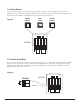
1.4 ALARM DISABLE The alarm disable switch, located on the front panel (figure 3), operates by removing DC common from the “Alarm Coil Power” terminals. Disabling of alarms does not inhibit any function of the Model 12B digital control modules. The digital display, alarm LEDs and on board alarm relays remain active. Figure 3 POWER ON/OFF FUSE 2 AMP ALARM DISABLE FUSE PRESS 812-N4X 1.
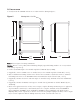
1.6 INSTALLATION 1. Securely mount the 812-N4X enclosure in accordance with the drawing in figure 5. Figure 5 Mounting Holes - 7/16" Dia. 20.75 19.25 12.5 9.75 15.75 Note: Reference figure 6 for wiring terminations. Caution: Observe correct polarity when terminating all input/output field wiring. Failure to do so may result in circuit damage on power up. 2. Connect 85-264 VAC input to the terminal strip labeled “VAC IN” (L1, N, GND). 3.
. If applicable, connect a normally open momentary remote mounted switch to the terminal strip labeled “Alarm Reset”. Figure 6 Zone Programming Jumpers VDC IN VAC IN L1 N GND RS-485 A (+) B (–) Shld CH1 CH2 CH8 4-20mA Fault Alm 1 Alm 2 Alm 3 Sensor Out Alm Reset mA Com NO/NC Com NO/NC Com NO/NC Com NO/NC VDC Alm Pwr VDC VAC L1 N GND Alm Coil Pwr 1.7 START UP Upon completion of all field wiring: Depress the power switch located on the front panel.
1.9 SPARE PARTS LIST Part # 5026 0295 3618-MAP-24 0224 2812 0298 320-3217-1 320-3217-2 2806 2807 3280 Description Multiple alarm relay circuit 5 amp micro fuse 130 watt, 24 VDC switcher power supply Gold plated jumper tab 24 VDC lamp for power and alarm disable switch 2 amp 3AG slow blow fuse Power switch assembly Alarm Disable switch assembly Green switch cap (for power switch) Red switch cap (for alarm disable switch) Fuse holder 1.10 WARRANTY Detcon Inc.