Model 880RA-N4X Model 880RS-N4X Graphic Remote Display Model 880RS-N4X Serial Remote Display www.detcon.com Operator’s Installation and Instruction Manual DETCON, Inc. 3200 Research Forest Dr., A-1 The Woodlands, Texas 77381 Ph.281.367.4100 / Fax 281.298.2868 www.detcon.com February 26, 2009 • Document # 3489 • Revision 0.
880R-N4X Page intentionally blank 880R-N4X Instruction Manual ii
880R-N4X Table of Contents Introduction .............................................................................................................................................1 1.0 2.0 System Configuration .............................................................................................................................1 2.1 Touch Panel Graphic Display............................................................................................................... 1 2.2 Specifications ........
880R-N4X Page intentionally blank Shipping Address: 3200 A-1 Research Forest Dr., The Woodlands Texas 77381 Mailing Address: P.O. Box 8067, The Woodlands Texas 77387-8067 Phone: 888.367.4286, 281.367.4100 • Fax: 281.292.2860 • www.detcon.com • sales@detcon.
880R-N4X 1.0 Introduction The Detcon Model 880 Remote Display unit is specifically designed to serve as a Remote Monitor for the Model 880 PLC Control Units. The Model 880RA-N4X is designed to work with the Model 880 Analog versions, and the Model 880RS-N4X is designed to work with the Model 880 Serial versions PLC Graphic Controllers. The NEMA 4X rated enclosure is rain tight and suitable for outdoor locations in electrically nonhazardous environments.
880R-N4X P1 F1 N J1 J2 1 2 3 4 5 6 + + 24V . . . . L1 NOT Used + Dedicated power supply recommended PWR CPU TxD RxD 1A I Ground VAC (L1) NEU (L2) TXD+ TXDRXD+ RXD0V O TERMINAL INPUT Figure 2 Unit overview 2.
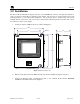
880R-N4X 3.0 Installation The Detcon Model 880 Remote Display enclosure is rated NEMA 4X, which is rain tight and suitable for outdoor locations in electrically non-hazardous environments. The enclosure is equipped with four (4) wallmounting brackets for easy wall mount installations. Care should be given to prevent sharp objects from colliding with the touch screen. The screen can be cleaned with a mild detergent and a lint free cloth. Never use an abrasive cleaner on the display. 1.
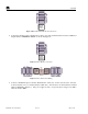
TXD+ TXDRXD+ RXD0V 880R-N4X REMOTE OUTPUT Figure 4 Main 880 terminal blocks and connections TXD+ TXDRXD+ RXD0V 4. Connect the RS-422 Serial communications cable to the input terminal blocks inside the 880 Remote Display labeled “TERMINAL INPUT” as shown in (Figure 5). TERMINAL INPUT TXD+ TXDRXD+ RXD0V TERMINAL INPUT 0V RXDRXD+ TXDTXD+ MAIN 880 REMOTE OUTPUT Figure 5 Remote RS-422 connections TXD+ TXDRXD+ RXD0V CUSTOMER SUPPLIED WIRING REMOTE DISPLAY Figure 6 Remote Interconnect Wiring 5.
880R-N4X 1A I VAC (L1) Ground NEU (L2) O Figure 7 Typical Input Power connections Upon completion of all field wiring, apply power to the Main 880 and the 880 Remote Display. The unit will go through a brief initialization and display the “Main Screen” (Figure 15). The “AC” box on the display should be green to show that AC is attached to the unit. The “USB” box gray to indicate no USB drive is attached. 4.0 Setup 4.
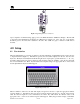
880R-N4X maximum, and current box. These boxes show the lower limit, upper limit, and current value of the number being entered. Numeric entries outside of these restrictions will not be accepted. Figure 9 Input Keypad The display screen also contains a number of “buttons”. These “buttons” act as toggle switches that change state when activated by the wand. These buttons will indicate the change in state by some obvious means such as a change in color, name, or both (i.e.
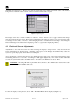
880R-N4X Figure 11 Main Menu From the Main Menu select the “Setting” button to enter the “Setting” Screen (Figure 12). Figure 12 Screen Settings From the “Setting” Screen, select the “Adjust Clock” button to adjust the clock (Figure 13) or the “Adjust Display” button to adjust the Display Screen (Figure 14). Figure 13 Clock Adjust Screen To adjust the Time and Date use the arrow keys. Once the correct time and date have been set, select “OK” to close the screen.
880R-N4X Figure 14 Adjust Display Screen 4.3 880 Remote Display Setup The remote display must be setup to match the main 880. The screens are duplicates of the Main 880; therefore, the setup is accomplished in much the same manner as the main unit. If the 880 Remote Display is not set up to match the Main 880, the resulting displays will be inconsistent and erroneous. 1) From the “Main Screen” (Figure 15), enter the “System Configuration Screen” by touching the “System Configuration” box with the wand.
880R-N4X Figure 16 Analog Configuration Screen NOTE: The System Configuration Screens differ only slightly between the Analog and Serial units. Figure 17 Serial Configuration Screen 3) Use the wand to select the “FACILITY NAME” box. A keyboard will appear to allow input of the facility name (Figure 18). The facility name can be any alphanumeric string of no more than 40 characters. After the facility name has been entered, use the ‘ENTER’ key to transfer the string to the “System Configuration Screen”.
880R-N4X Figure 18 Inputting the Facility Name 4) Select the “TOTAL # OF CHANNELS” Box and input the number of channels that are attached to the Main 880. This number must match the number entered in the Main 880. Figure 19 Inputting the number of channels 5) Select the “EXIT” box to exit the “System Configuration Screen” and return to the “Main Screen”.
880R-N4X Figure 20 Channel Detail Screen a) Select “Channel Description”. The keyboard will appear, allowing the input of the Channel Tag Name, or a brief description of the sensor, up to 20 characters maximum. The “Channel Description” here must match the “Channel Description” entered at the Main 880. b) Select “Gas Type”, and input the gas type of the sensor. (i.e., H2S, LEL, CO2, etc.) Up to 10 characters maximum. The “Gas Type” entered here must match the “Gas Type” entered at the Main 880.
880R-N4X the sensor is in an alarm condition, the corresponding “FLT”, “ALM1”, “ALM2”, “ALM3”, or “COM” will blink to signify that condition. Touching a channel number (Ch-X) will open the corresponding channels “Channel X Details Screen”. This screen will provide more information on the selected channel. Near the top left of the screen, just below the Detcon Logo, there will be 2 to 9 selection buttons (Labeled “18,” “9-16,” “17-24,” etc.
880R-N4X 5.2 Channel X Details Screen When selected, each channel will open its own detail screen (Figure 22). This screen provides a graphic representation of the last 30 minutes of the sensor’s activity. The display allows the user to move forward or backward in the graphic to display activity before or after the displayed time using the arrow keys in the upper left of the graphic display.
880R-N4X When alarms are initiated, the unit stores information about these alarms into memory. If a USB Drive is installed in the back of the display, this information is written onto the drive for permanent storage (USB Drive sold separately). The information can also be viewed on the “Alarm History Screen” by using the wand to select the “Alarm History” button on the Main Screen. The Alarm History Screen displays Fault and Alarm events throughout operation of the unit (Figure 23).
880R-N4X Appendix A Drawings and Diagrams 1. Remote Display Dimensional Overview 2. Remote Display Component Layout 3. Remote Display Wiring Diagram 880R-N4X Instruction Manual Rev. 0.
880R-N4X Page intentionally blank Shipping Address: 3200 A-1 Research Forest Dr., The Woodlands Texas 77381 Mailing Address: P.O. Box 8067, The Woodlands Texas 77387-8067 Phone: 888.367.4286, 281.367.4100 • Fax: 281.292.2860 • www.detcon.com • sales@detcon.com 880R-N4X Instruction Manual Rev. 0.