
Instruction Manual
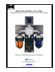
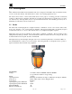

AV2-C1D2C
AV2-C1D2C Instruction Manual Rev. 2.0 Page 4 of 4
STROBE 1 STROBE 2
HORN
L1 L2
G
L1 L1L2 L2
GG
Customer Input Wiring
L1 Siren
L1 Strobe 1
L2 (Neu)
GND
L1 Strobe 2
STROBE 1 STROBE 2
HORN
L1 L2
G
L1 L1L2 L2
GG
Customer Input Wiring
L1 Siren
L1 Strobe 1
L2 Strobe 1
GND
L1 Strobe 2
L2 Siren
L2 Strobe 2
Optional
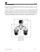
Standard wiring shown on
left.
Optional: Removal of jumper
between 5,6, and 7 for
discrete annunciator wiring
shown on right.
Ground can be connected to
the Ground Screw or the
connector.
Blk
Blk
Blk
Wht
Wht
Wht
Grn/Ylw
Blk
Blk
Blk
Wht
Wht
Wht
Grn/Ylw
Wht
Figure 4 120/240VAC Wiring diagram
3.0 Parts List
Detcon Part # Description
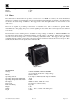
500-003198-000 Alarm System Terminal Board
356-35W006-120 120 VAC Hazardous location vibrating siren
356-35W006-240 240 VAC Hazardous location vibrating siren
354-1516X6-120 151XST – 120VAC Strobe, Ext Ground (X represents color of lamp)
354-1516X6-240 151XST – 240VAC Strobe, Ext Ground (X represents color of lamp)
Strobe colors: Red (2), Amber (4), Green (5), Blue (6), Magenta (7), and Clear (9)
4.0 Warranty
Detcon Inc., as manufacturer, warrants under intended normal use each new AV2-C1D2M Alarm station to be
free from defects in material and workmanship for a period of one year. The warranty period begins from the
date of shipment to the original purchaser and ends one year thereafter. All warranties and service policies are
FOB the Detcon Inc. facility located in The Woodlands, Texas.
Shipping Address: 3200 A-1 Research Forest Dr., The Woodlands Texas 77381
Mailing Address: P.O. Box 8067, The Woodlands Texas 77387-8067
Phone: 888.367.4286, 281.367.4100 • Fax: 281.292.2860 •
www.detcon.com • sales@detcon.com