detcon inc. Detcon MicroSafe™ FP-524C Combustible Gas Sensor (0-100% LEL) Operator’s Installation & Instruction Manual August 12, 2010 • Document #2265 • Version 1.8 CAUTION: Before operating the Model FP-524C sensor, read this manual thoroughly and verify that the configuration of default factory settings are appropriate and correct for your application.
Table of Contents 3.0 Description 3.1 Principle of Operation 3.2 Application 3.3 Specifications 3.4 Operating Software 3.5 Installation 3.6 Start-up 3.7 Target Gas and Calibration Gas Selection 3.8 Calibration 3.9 Status of Programming, Calibration Level, Bridge Voltage, and Sensor Life 3.10 Program Features 3.11 Display Contrast Adjust 3.12 Trouble Shooting Guide 3.13 Spare Parts List 3.14 Warranty 3.15 Service Policy 3.16 Software Flow Chart Model FP-524C Combustible Gas Sensor PG.
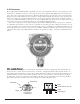
.0 DESCRIPTION Detcon MicroSafe™ Model FP-524C, combustible gas sensors are non-intrusive “Smart” sensors designed to detect and monitor combustible gas in air over the range of 0-100% lower explosive limit (LEL). One of the primary features of the sensor is its method of automatic calibration which guides the user through each step via instructions displayed on the backlit LCD. The sensor output is a standard 4-20 mA signal.
3.0.2 Microprocessor Control Circuit The control circuit is microprocessor based and is packaged as a plug-in field replaceable module, facilitating easy replacement and minimum down time. Circuit functions include a basic sensor pre-amplifier, sensor temperature control, on-board power supplies, microprocessor, back lit alpha numeric display, magnetic programming switches, and a linear 4-20 mA DC output.
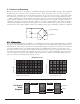
3.1 PRINCIPLE OF OPERATION Method of detection is by a controlled rate of diffusion/adsorption. Air and gas diffuse through a sintered stainless steel filter and contact both the active and reference detector beads. The surface of the active detector promotes oxidation of the combustible gas molecule while the reference detector has been treated not to support this oxidation. The reference detectors serve as a means to maintain zero stability over a wide operating temperature range.
3.2 APPLICATION Model FP-524C MicroSafe™ sensors are designed to detect and monitor combustible gas in ambient air in the range of 0-100% LEL. Minimum sensitivity and scale resolution is 1%. Operating temperature range is -40° F. to +175° F. While the sensor is capable of operating outside these temperatures, performance specifications are verified within the limit. 3.2.1 Sensor Placement/Mounting Sensor location should be reviewed by facility engineering and safety personnel.
a) Current Status 02. Calibration Mode a) Zero b) Span 03. Program Menu a) Program Status b) Target gas selection (gas K factor) c) Calibration gas selection (cal K factor) d) Calibration Level e) Set Bridge Volts 3.4.1 Normal Operation In normal operation, the display tracks the current status of the sensor and gas concentration and appears as: “0 % LEL”. The mA current output corresponds to the monitoring level and range of 0-100% = 4-20 mA. 3.4.
3.5 INSTALLATION Optimum performance of ambient air/gas sensor devices is directly relative to proper location and installation practice. 3.5.1 Field Wiring Table (4-20 mA output) Detcon Model FP-524C combustible gas sensor assemblies require three conductor connection between power supplies and host electronic controllers. Wiring designators are + (DC), – (DC) , and mA (sensor signal). Maximum single conductor resistance between sensor and controller is 10 ohms.
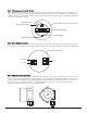
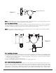
Plug any unused ports. “T” Figure #1 Drain EYS Seal Fitting Note: In all installations, the sensor element in SS housing points down relative to grade (Fig. 1). Improper sensor orientation may result in false reading and premature sensor damage. 3.5.4 Local Electrical Codes Sensor and transmitter assemblies should be installed in accordance with all local electrical codes. Use appropriate conduit seals. Drains are required at the bottom of vertical conduit runs.
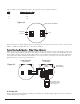
There is a limit 0.5 ohm maximum resistance drop per wire over the seperation distance. AWG 20 18 16 14 Maximum Seperation (feet) 50 75 125 175 Figure #3 Base Connector Board 4-20 mA Output mA VDC Power In BLU YEL BLK WHT Sensor Reference figure 4 for wiring diagram. Also note the jumper that is required on the remote sensor connector board. Failure to install this jumper will cause a sensor fault condition.
a) FP-524C “Fault” LED is off. b) A temporary upscale reading may occur as the sensor heats up. This upscale reading will clear to “0” % within 1-2 minutes of turn-on, assuming there is no gas in the area of the sensor. Note 1: If the display contrast needs adjustment, refer to section 3.11. Note 2: If the sensor has been installed using the remote mounting configuration as described in section 3.5.5, the sensor bridge voltage must be adjusted after initial power up.
labeled “PGM 1” and “PGM 2” allow for complete calibration and programming without removing the enclosure cover, thereby eliminating the need for area de-classification or the use of hot permits. Magnetic Programming Tool Figure #5 A magnetic programming tool (see figure 5) is used to operate the switches. Switch action is defined as momentary contact, 3 second hold, and 30 second hold. In momentary contact use, the programming magnet is waved over a switch location.
TABLE 1a (alphabetical listing) Gas Acetaldehyde Acetic Acid Acetic Anhydride Acetone Acetylene Alkyl Alcohol Ammonia n-Amyl Alcohol Aniline Benzene Biphenyl 1,3-Butadiene Butane iso-Butane Butene-1 cis-Butene-2 trans-Butene-2 n-Butyl Alcohol iso-Butyl Alcohol tert-Buty-alcohol n-Butyl Benzene iso-Butyl Benzene n-Butyric Acid Carbon Disulphide Carbon Monoxide Carbon Oxysulphide Cyanogen Cyclohexane Cyclopropane K Gas Decane Diethylamine Dimethylamine 2,3-Dimethylpentane 2,2-Dimethylpropane Dimethylsulphid
3.7.2 Verification of Target Gas and Calibration Gas Configuration Verification of target gas and calibration gas configuration is obtained via interaction with the menu driven display which requires the use of a programming magnet. Material Requirements: Detcon PN 3270 MicroSafe™ Programming Magnet a) First, enter the programming menu by holding the programming magnet stationary over “PGM 2” for 30 seconds until the display reads “VIEW PROG STATUS”, then withdraw the magnet.
b) Next, scroll to the “SET CAL FACTOR” listing and then hold the programming magnet over “PGM 1” for 3 seconds. The menu item appears as “CAL FACTOR #.##”. Use the programming magnet to make an adjustment to “PGM 1” to increase or “PGM 2” to decrease the display reading until the reading is equal to the desired K factor. Save value by holding the programming magnet over “PGM1” for 3 seconds.
b) If the calibration gas level setting is equal to your calibration span gas concentration, proceed to item “f”. If not, adjust the calibration gas level setting so that it is equal to your calibration span gas concentration, as instructed in items “c” through “e”. c) Enter the programming menu by holding the programming magnet stationary over “PGM 2” for 30 seconds until the display reads “VIEW PROG STATUS”, then withdraw the magnet.
3.9 STATUS OF PROGRAMMING, TARGET GAS, CALIBRATION GAS, CALIBRATION LEVEL, SENSOR LIFE, AND BRIDGE VOLTAGE The programming menu has a programming status listing that allows the operator to view the gas, range, and software version number of the program, as well as target and calibration gas settings, calibration gas level setting, bridge voltage, and estimated remaining sensor life. The programming menu also allows the changing of target gas and calibration gas settings (see section 3.
Fail-Safe/Fault Supervision Model FP-524C MicroSafe™ sensors are programmed for fail-safe operation. Any of the following fault condition will illuminate the fault LED, and cause the display to read its corresponding fault condition: “SENSOR FAULT”, “SIGNAL FAULT”, “HEATER FAULT”, or “CAL FAULT”. A “Sensor Fault”, “Signal Fault”, “Cal Fault”, and “Heater Fault”, will also cause the mA output to drop to zero (0) mA.
3. Check validity of cal gas via the expiration date and use pull tube if necessary. 4. Check for obstructions through stainless steel sinter element (including being wet) 5. Replace plug-in sensor if Sensor Life is < 50%. 6. Check area for presence of sensor poisoning gases such as silicon grease vapors, HMDS, high H2S, chlorine or chlorinated compounds if sensor failures persist. Drifting Zero 1.
3.
3.16 SOFTWARE FLOW AUTO ZERO LEGEND PGM1 - program switch location #1 PGM2 - program switch location #2 (M) - momentary pass of magnet (3) - 3 second hold of magnet (30) - 30 second hold of magnet INC - increase DEC - decrease # - numeric value AUTO SPAN PGM1 (3) PGM2 (3) CALIBRATION 1-ZERO 2-SPAN PGM1 (3) NORMAL OPERATION PGM2 (30) VIEW PROG STATUS SET GAS FACTOR SET CAL FACTOR PGM1 (3) PGM2 (M) PGM1 (3) PGM2 (M) PGM1 (3) PGM2 (M) PGM2 (3) PGM2 (3) PGM2 (3) GAS FACTOR #.