
INSTRUCTION MANUAL Owner's manual


Model FP-524D
FP-524D Instruction Manual Rev. 1.4 Page 8 of 39
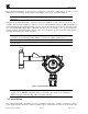
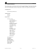
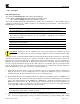
Proper electrical installation of the gas sensor is critical for conformance to Electrical Codes and to avoid
damage due to water leakage. Refer to Figure 10 and Figure 11 for proper electrical installation.
NOTE:
If a conduit run exits the secondary port, repeat the installation technique shown in
Figure 10.
In Figure 10, the drain allows H
2
O condensation inside the conduit run to safely drain away from the sensor
assembly. The electrical seal fitting is required to meet the National Electrical Code per NEC Article 500-3d
(or Canadian Electrical Code Handbook Part 1 Section 18-154). Requirements for locations of electrical seals
are covered under NEC Article 501-5. Electrical seals also act as a secondary seal to prevent water from
entering the wiring terminal enclosure. However, they are not designed to provide an absolute watertight seal,
especially when used in the vertical orientation.
NOTE:
A conduit seal is typically required to be located within 18" of the J-Box and Sensor
Assembly. Crouse Hinds type EYS2, EYD2 or equivalent are suitable for this purpose.
NOT
E:
The Detcon Warranty does not cover water damage resulting from water leaking into
the enclosure.
Drain
Conduit
"T"
EYS Seal Fitting
PGM 1
PGM 2
MODEL FP-524D
HOUSTON, TEXAS
FLT 1 2 CAL
MicroSafe LEL Gas Sensor
ALM ALM
TM
Figure 10 Typical Installation
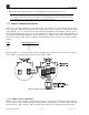
NOTE:
Any unused ports should be blocked with suitable ¾” male NPT plugs. Detcon
supplies one ¾” NPT male plug with each J-box enclosure. If connections are other than ¾”
NPT, use an appropriate male plug of like construction material.
2.6 Field Wiring
Detcon Model FP-524D combustible gas sensor assemblies require three conductor connections between
power supplies and host electronic controller’s 4-20mA output. A 250 ohm load resistor is needed on the 4-20