INSTRUCTION MANUAL Detcon Model FP-700 FP-700 Combustible Gas Sensor 0-100% LEL 0-50% LEL DETCON, Inc. 4055 Technology Forest Blvd., The Woodlands, Texas 77381 Ph.281.367.4100 / Fax 281.298.2868 www.detcon.com February 28, 2014 • Document #3168 • Revision 3.
Model FP-700 This page left intentionally blank Model FP-700 ii
Model FP-700 Table of Contents 1. Introduction ..................................................................................................................................................1 1.1 Description.......................................................................................................................................... 1 1.2 Sensor Electronics Design .................................................................................................................. 2 1.
Model FP-700 Table of Figures Figure 1 Sensor Cell Construction ....................................................................................................................... 1 Figure 2 Wheatstone Bridge................................................................................................................................. 2 Figure 3 Response Curves....................................................................................................................................
Model FP-700 1. Introduction 1.1 Description Detcon Model FP-700 combustible gas sensors are non-intrusive “Smart” sensors designed to detect and monitor combustible gases in air. Range of detection is 0-100% LEL or 0-50% LEL. The sensor features an LED display of current reading, fault and calibration status. The unit is equipped with standard analog 4-20mA and Modbus™ RS-485 outputs.
Model FP-700 Senso r C ell Inp u t V o ltag e C o m p ensato r / Ref erenc e B ead Z ero Adj u st D etec to r / Ac tive B ead O u tp u t Figure 2 Wheatstone Bridge Performance Characteristics The detector elements maintain good sensitivity to combustible gas concentrations in the Lower Explosive Limit (LEL) range, as shown in the response curves in Figure 3. However, for gas concentrations significantly above the LEL range (100% LEL = 5% by volume Methane), the bridge output begins to decrease.
Model FP-700 LED Display detcon inc. MODEL FP-700 Program Switch #1 Program Switch #2 LEL Sensor Splashguard Adapter Lockdown Set-Screw Figure 5 Sensor Assembly Front View 1.
Model FP-700 1.4 Plug-in Replaceable Sensor The Detcon combustible gas sensor is a poison-resistant and field proven design. It is packaged as true plug-in replaceable type sensor with over-sized gold-plated connections that eliminate corrosion problems. It can be accessed and replaced in the field very easily by releasing the locking screw and unthreading the housing bottom. The Detcon combustible gas sensor has an infinite shelf life, and is supported by a 2-year warranty.
Model FP-700 2. Installation 2.1 ATEX Operational Guidelines for Safe Use 1. Install sensor only in areas with classifications matching with those described on the ATEX approval label. Follow all warnings listed on the label. Figure 8 ATEX Approval Label 2. Ensure that the sensor is properly threaded into a suitable explosion-proof rated junction box with a downward pointing female ¾” NPT threaded connection.
Model FP-700 2.2 Sensor Placement Selection of sensor location is critical to the overall safe performance of the product. Six factors play an important role in selection of sensor locations: (1) Density of the gas to be detected (2) Most probable leak sources within the industrial process (3) Ventilation or prevailing wind conditions (4) Personnel exposure. (5) Maintenance access. (6) Personal Exposure.
Model FP-700 When possible in an area void of high wind, accumulating dust, rain or splashing from hose spray, direct steam releases, and continuous vibration. If the sensor cannot be mounted away from these conditions then make sure the Detcon Harsh Environment Splashguard accessory is used. Do not mount in locations where temperatures will exceed the operating temperature limits of the sensor.
Model FP-700 5.5" 4.95" 3.675" 5.25" Spacer Ø0.265" x2 Mounting Holes Mounting Bolt 3/4" NPT (Detcon's Junction-Box shown) 12.5" 5.53" Use Spacers to move the J-Box and Sensor Assembly away from the wall at least 0.25-0.5" to allow access to Sensor detcon inc. MODEL FP-700 7.855" mounting surface) Explosion Proof Enclosure Junction-Box Wall (or other 8-32 Thread Ground Point Sensor Assembly LEL Sensor Splash Guard 2" 2.125" Figure 9 Outline and Mounting Dimensions 2.
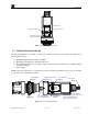
Model FP-700 NOTE: A conduit seal is typically required to be located within 18" of the J-Box and Sensor Assembly. Crouse Hinds type EYS2, EYD2 or equivalent are suitable for this purpose. Conduit Plug any unused ports "T" EYS Seal Fitting Explosion Proof Housing (J-Box) Drain Customer Supplied Wiring Explosion Proof Junction Box (+) (-) mA N/U A(+) B(-) detcon inc. FP-700 Sensor Assembly Red Blk Grn Blu Wht A(+) B(-) (+) (-) Mount TPM in Explosion Proof Enclosure to ground unit properly.
Model FP-700 Over-Current Protection 0.723mm 3A 0.812mm 5A 1.024mm 7A 1.291mm 10A 1.628mm 20A Table 1 Protection vs. Wire Gauge AWG 22 20 18 16 14 Wire Dia. NOTE 1: Wiring table is based on stranded tinned copper wire and is designed to serve as a reference only. NOTE 2: Shielded cable is required for installations where cable trays or conduit runs include high voltage lines or other possible sources of induced interference. Separate conduit runs are highly recommended in these cases.
Model FP-700 NOTE: If the 4-20mA output is not being used, the Green wire from the sensor must be connected to the Black wire at the (-) terminal on the Transient Protection Module to ensure RS-485 communication is not disrupted by a 4-20mA Fault. a) If applicable, terminate the RS-485 serial wiring as shown in Figure 11.
Model FP-700 Initial operational tests are complete. Detcon FP-700 combustible gas sensors are factory calibrated prior to shipment, and should not require significant adjustment on start up. However, it is recommended that a complete calibration test and adjustment be performed 16 to 24 hours after power-up. Refer to zero and span calibration instructions in Section 3.4.Operation 3. Operation 3.
Model FP-700 detcon inc. LED Display MODEL Program Switch #1 FP-700 Program Switch #2 LEL Sensor Figure 13 Magnetic Programming Switches NOTE: While in the Program Mode, if there is no magnetic switch interaction after 4 consecutive menu scrolls, the sensor will automatically revert to normal operating condition. While changing values inside menu items, if there is no magnet activity after 3-4 seconds the sensor will revert to the menu scroll. (Exception to this is with “Signal Output Check” mode.
Model FP-700 Sensor Bridge Voltage Gas Factor Cal Factor 4-20mA Output Input Voltage Supply Operating Temperature Set AutoSpan Level Set Gas Factor Set Cal Factor Set Serial ID Set Bridge Voltage Signal Output Check Restore Default Settings Software Flowchart Normal Operation PGM1 (3) PGM2 (10) PGM1 (3) PGM2 (3) Calibration Mode (Auto Zero) Calibration Mode (Auto Span) View Sensor Status Auto Time-Out PGM1/2 (M) PGM1/2 (3) Set AutoSpan Level Set Gas Factor Auto Time-Out PGM1/2 (M) PGM1/2 (3) AutoTime
Model FP-700 3.3 Normal Operation In normal operation, the ITM Display continuously shows the current sensor reading, which will normally appear as “ 0 ”. Once every 60 seconds the LED display will flash the sensor’s measurement units and gas type (i.e. % LEL). If the sensor is actively experiencing any diagnostic faults, a “Fault Detected” message will flash on the ITM display every 60 seconds.
Model FP-700 Zero Cal. . .Setting Zero. . . Zero Saved (each will scroll twice) d) Remove the zero gas and calibration adapter, if applicable. 3.4.2 AutoSpan The AutoSpan function is used to span calibrate the sensor. Span adjustment is recommended at 50% LEL. NOTE: Before performing AutoSpan Calibration, verify that the AutoSpan level matches the span calibration gas concentration as described in Section 3.5.3Set AutoSpan Level.
Model FP-700 b) From Normal Operation, enter Calibration Mode by holding the programming magnet over PGM1 for 3-4 seconds. Note, the “◄” prompt will show that the magnetic switch is activated during the 3-4 second hold period. The display will then scroll “PGM1=Zero…PGM2=Span”. Hold the programming magnet over PGM2 for 3-4 seconds once the “►” prompt appears, until the Display starts to scroll “Span Cal” to execute AutoSpan (or allow to timeout in 5 seconds if AutoSpan is not desired).
Model FP-700 Modbus output. 3.5 Program Mode Program Mode provides a View Sensor Status menu to check operational and configuration parameters. Program Mode also provides for adjustment of the AutoSpan Level, Bridge Voltage, Gas Factor, Cal Factor, and Serial ID. Additionally, it includes the Restore Factory Defaults and Signal Output Check diagnostic functions.
Model FP-700 Range of Detection The menu item appears as: “Range XXX” Serial ID address. The menu item appears as: “Serial ID XX” AutoSpan Level. The menu item appears as: “Auto Span Level XX” Days From Last AutoSpan The menu items appears as: “Last Cal XX days” Remaining Sensor Life The menu item appears as: “Sensor Life 100%” Sensor Bridge Current The menu item appears as: “Bridge XXXmA Sensor Bridge Voltage The menu item appears as: “Bridge X.XXVDC Gas Factor The menu item appears as: “Gas Factor X.
Model FP-700 The menu item appears as: “Set AutoSpan Level”. From the Set AutoSpan Level text scroll, hold the magnet over PGM1 or PGM2 until the “◄” prompt appears and continue to hold the magnet in place for an additional 3-4 seconds (until the display starts to scroll “Set Level”). The display will switch to “XX“ (where XX is the current gas level). Swipe the magnet momentarily over PGM2 to increase or PGM1 to decrease the AutoSpan Level until the correct level is displayed.
Model FP-700 Butane iso-Butane Butene-1 cis-Butene-2 trans-Butene-2 n-Butyl Alcohol iso-Butyl Alcohol tert-Butyl-Alcohol n-Butyl Benzene iso-Butyl Benzene n-Butyric Acid Carbon Disulphide Carbon Monoxide Carbon Oxysulphide Cyanogen Cyclohexane Cyclopropane 1.71 1.93 2.20 2.06 1.97 2.91 1.89 1.34 3.18 3.12 2.63 5.65 1.32 1.07 1.12 2.43 1.
Model FP-700 From the Set Gas Factor text scroll, hold the magnet over PGM1 or PGM2 until the “◄” prompt appears and continue to hold the magnet in place for an additional 3-4 seconds (until the display starts to scroll “Set Factor”). The display will then switch to “ X.XX“ (where X.XX is the current cal factor). Swipe the magnet momentarily over PGM2 to increase or PGM1 to decrease the gas factor level until the correct value is displayed.
Model FP-700 Move to another menu item by executing a momentary hold, or, return to Normal Operation via automatic timeout of about 15 seconds (the display will scroll “Set Bridge Voltage” 4 times and then return to Normal Operation). 3.5.8 Signal Output Check Signal Output Check provides a simulated 4-20mA output and RS-485 Modbus™ output. This simulation allows the user to conveniently perform a functional system check of their entire safety system.
Model FP-700 NOTE: The following must be performed in order before the sensor can be placed in operation. AutoSpan Level = 50 %LEL. AutoSpan level must be set appropriately by the operator (Section 3.5.3). Gas Factor = 1.0. The Gas Factor must be set appropriately by the operator (Section 3.5.4). Cal Factor = 1.0. The Cal Factor must be set appropriately by the operator (Section 3.5.5). AutoZero: AutoZero Settings are lost and user must perform new AutoZero (Section 3.4).
Model FP-700 is not employed for a Temperature Fault and AutoSpan Reminder Fault. For all diagnostic faults, the associated RS-485 Modbus™ fault register will be flagged to alert the user digitally. NOTE: Refer to the Troubleshooting Guide section 6 for guidance on fault conditions. Zero Fault If the sensor drifts below –10% LEL, the “Zero Fault” will be declared. A “Zero Fault” will cause a “Fault Detected” message to scroll once a minute on the ITM display and drop the 4-20mA output to 0mA.
Model FP-700 register bit for Memory Fault will be set and will not clear until the fault condition has been cleared. If a Memory Fault occurs, the 4-20mA signal will be set at 0mA until the fault condition is resolved. 4-20mA Loop Fault If the sensor detects a condition where the 4-20mA output loop is not functional (high loop resistance or failed circuit function) a “4-20mA Fault” is declared. A “4-20mA Fault” will cause the “Fault Detected” message to scroll once a minute on the ITM display.
Model FP-700 4. RS-485 Modbus™ Protocol Model DM-700 sensors feature Modbus™ compatible communications protocol and are addressable via the program mode. Other protocols are available. Contact the Detcon factory for specific protocol requirements. Communication is two wire, half duplex 485, 9600 baud, 8 data bits, 1 stop bit, no parity, with the sensor set up as a slave device. A master controller up to 4000 feet away can theoretically poll up to 256 different sensors.
Model FP-700 FC REG Content Description R/W Content Definition Meaning Function dependent on value of 40006 (See Special Register Table 4) Function dependent on value of 40006 (See Special Register Table 4) Function defendant on value of 40006 (See Special Register Table 4) Idle Zero Calibration Started Span Calibration Started Span Set Span Calibration Unsuccessful Set Zero Set Span Signal simulation mode Set FP Bridge Voltage Set TP Heater Power Set IR Gain Value 03/ 06 40012 Special #2 R/W 03 4
Model FP-700 5. Service and Maintenance 5.1 Calibration Frequency In most applications, quarterly to biannual zero and span calibration intervals will assure reliable detection. However, industrial environments differ. Upon initial installation and commissioning, close frequency tests should be performed, weekly to monthly. Test results should be recorded and reviewed to determine a suitable calibration interval. 5.2 Visual Inspection The Sensor should be inspected annually.
Model FP-700 e) Thread the Bottom Housing onto the ITM to a snug fit and tighten the locking setscrew using the M1.5 Allen wrench. Reinstall the splashguard. f) With the new plug-in sensor physically installed, two menu functions are required to be performed. 1) The Set Bridge Voltage function must be performed to match the new sensor with the ITM (Section 3.5.6). 2) Perform a successful AutoZero and AutoSpan to match the new sensor with the ITM (Section 3.4). 5.
Model FP-700 6. Troubleshooting Guide Refer to the list of Failsafe Diagnostic features listed in Section 3.6.2 for additional reference in troubleshooting activities. Listed below are some typical trouble conditions and their probable cause and resolution path. Figure 16 Plug-in Sensor (Bottom View) Open Sensor Fault Probable Cause: Plug-in sensor has failed. Remove plug-in sensor and verify resistance between PIN 4 and PIN 5 and PIN 4 and PIN 2using an ohmmeter.
Model FP-700 Check Bridge Voltage (should be 2.7 +/- 0.2VDC). Check validity of span gas and flow rate (check MFG date on cal cylinder). If using Splashguard with Integral Cal Port, must use Calibration Wind Guard or air movement can compromise span gas delivery. Make sure correct Cal Factor is set Check for obstructions through stainless steel sinter element (including being wet). Replace the plug-in sensor.
Model FP-700 Restore Factory Defaults - This will clear the processor’s memory and may correct problem. Remember to re-enter all customer settings for range and cal gas level after Restore Factory Defaults. If problem persists, replace the Intelligent Sensor Module. Unreadable Display If due to excessive sunlight, install a sunshade to reduce glare. Nothing Displayed – Transmitter not Responding Verify condulet has no accumulated water or abnormal corrosion.
Model FP-700 7. Customer Support and Service Policy Detcon Headquarters Shipping Address: 4055 Technology Forest Blvd., The Woodlands Texas 77381 Mailing Address: P.O. Box 8067, The Woodlands Texas 77387-8067 Phone: 888.367.4286, or 281.367.4100 Fax: 281.292.2860 • www.detcon.com • service@detcon.com • sales@detcon.com All Technical Service and Repair activities should be handled by the Detcon Service Department via phone, fax or email at contact information given above.
Model FP-700 8. FP-700 Sensor Warranty Plug-in Combustible Gas Sensor Warranty Detcon Inc. warrants, under normal intended use, each new plug-in combustible gas sensor (PN 370-201600700). The warranty period begins on the date of shipment to the original purchaser and ends 2 years thereafter. The sensor element is warranted free of defects in material and workmanship.
Model FP-700 9. Appendix 9.
Model FP-700 11"H x 6.1"W x 3.75"D; 280mmH x 155mmW x 96mmD (with junction box) Mounting holes (J-box) 5.5"; 140mm center to center Weight: 2 lbs; 0.907kg (sensor only) 6 lbs; 2.72kg (w/aluminum j-box) 9 lbs; 4.08kg (w/stainless steel j-box) Electrical Specifications Power Input: 11-30VDC Power Consumption: Normal operation = 68mA (<1.7 watt) Maximum = 85mA (2 watts) Inrush current: 1.
Model FP-700 9.
Model FP-700 10. Revision Log Revision 2.0 2.1 2.2 2.3 2.4 2.5 2.6 2.7 2.8 2.9 3.0 Date Changes made 02/29/2008 Previous issue 04/25/2011 Removed Teflon note in section 2.5. Added Revision Log Section 10. 07/11/11 Adding Inrush current information to specifications, drawing for aluminum condulet dimensional 04/16/12 Changed cable recommendation, updated the Modbus Register Map 01/07/13 Updated ATEX approvals label, updated EN standards that sensor assembly meets.
Model FP-700 This page left intentionally blank Shipping Address: 4055 Technology Forest Blvd., The Woodlands Texas 77381 Mailing Address: P.O. Box 8067, The Woodlands Texas 77387-8067 Phone: 888.367.4286, 281.367.4100 • Fax: 281.292.2860 • www.detcon.com • sales@detcon.com FP-700 Instruction Manual Rev. 3.
NA A JOB NO. SIZE 3168-1 6 DRAWING NO. REV Sensor Wiring to Junction Box Intelligent Transmitter Module (ITM) Transient Protection Module (TPM) P/N 500-003087-100 Customer Supplied Wiring (In) Power from and 4-20mA out to Control Device detcon inc.
Model FP-700 This page left intentionally blank Shipping Address: 4055 Technology Forest Blvd., The Woodlands Texas 77381 Mailing Address: P.O. Box 8067, The Woodlands Texas 77387-8067 Phone: 888.367.4286, 281.367.4100 • Fax: 281.292.2860 • www.detcon.com • sales@detcon.com FP-700 Instruction Manual Rev. 3.
3168-2 DRAWING NO. Wiring to Sensor Assembly If the Sensor is not mechanically grounded to the Junction Box, and external ground strap should be used to insure proper grounding. NOTES: Mount TPM in Explosion Proof Enclosure to ground unit properly. Mount to bottom of enclosure using 6-32 screws. Transient Protection Module (TPM) P/N 500-003087-100 mA N/U A(+) B(-) (+) (-) Explosion Proof Junction Box (+) (-) A SIZE Customer Supplied Wiring 3 4" PLANT: SERIAL NO. PROJECT NO. REQ. NO. P.O.
Model FP-700 This page left intentionally blank Shipping Address: 4055 Technology Forest Blvd., The Woodlands Texas 77381 Mailing Address: P.O. Box 8067, The Woodlands Texas 77387-8067 Phone: 888.367.4286, 281.367.4100 • Fax: 281.292.2860 • www.detcon.com • sales@detcon.com FP-700 Instruction Manual Rev. 3.
NA JOB NO. A SIZE 3168-3 6 DRAWING NO. REV 5.5" 5.2" 3 3.95" NPT Port Plug unused ports Detcon's Aluminum Explosion Proof Junction-Box (Condulet) 4" 5.825" 8-32 Threaded Ground Point Ø0.275" Mounting Hole 6-32 Threaded Ground Point 13" Typ detcon inc. 4.9" Typ. MODEL FP-700 Sensor Assembly LEL Sensor 0.3" Typ Splash Gaurd 2" NOTES: d et c o n , i n c . CLIENT: P.O. NO. REQ. NO. PROJECT NO. SERIAL NO.
Model FP-700 This page left intentionally blank Shipping Address: 4055 Technology Forest Blvd., The Woodlands Texas 77381 Mailing Address: P.O. Box 8067, The Woodlands Texas 77387-8067 Phone: 888.367.4286, 281.367.4100 • Fax: 281.292.2860 • www.detcon.com • sales@detcon.com FP-700 Instruction Manual Rev. 3.