Detcon Model FP Transmitter Test Fixture Operators Instruction Manual June 17, 2008 * Document 3389 * Revision 1.1 DETCON, Inc. 3200 Research Forest Dr., Building A-1 The Woodlands, Texas 77387 Ph. 713-559-9200 / Fax 281-298-2868 www.detcon.
Detcon Model FP Transmitter Test Fixture Table of Contents 1.0 Description 2.0 Features 3.0 Specifications 4.0 Operation 5.0 Test Fixture Calibration 6.
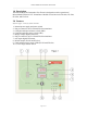
Detcon Model FP Transmitter Test Fixture 1.0 Description The Detcon Model FP Transmitter Test Fixture is designed to test the operation of Detcon Model FP Series LEL Transmitters. Models covered are series FP-424x, FP-524x, FP-550x, and FP-624x. 2.0 Features Reference figure 1 below for feature locations.
Detcon Model FP Transmitter Test Fixture 3.0 Specifications Compatible with the Following Models Model Series FP-424x, FP-524x, FP-550x, FP624x Input Power 100-240VAC, 50 / 60Hz Power Consumption < 17 Watts Digital Current Meter Accuracy: ± 0.3% FS Digital Voltage Meter Accuracy: ± 0.1% FS Warranty Two year Outputs Serial RS-485 Modbus™ 4.0 Operation Before using the test fixture, the technician should first be familiar with the operation of Detcon FP series combustible gas sensors.
Detcon Model FP Transmitter Test Fixture 3 - Check the bridge voltage. Insert DVM probes into the bridge “+” and “–“ test points. Adjust the VOLT potentiometer on the transmitter until you achieve a reading of 2.70V. Verify that the bridge voltage LED meter on the test fixture tracks closely with a reading of 2.7V (±0.1V). Verify adjustability to either side of 2.70V. 4 - Perform zero cal. Verify SW1 is in the “0” position. Insert DVM probes into the signal “+” and “–“ test points.
Detcon Model FP Transmitter Test Fixture b) Next, scroll to the “SET BRIDGE VOLTS” listing and then hold the programming magnet over “PGM 1” for 3 seconds. The menu item appears as “BRIDGE @ #.## VDC”. c) Use the programming magnet to make an adjustment to “PGM 1” to increase or “PGM 2” to decrease the bridge voltage. Set the voltage to 2.7 VDC. Note that the LED meter on the test fixture tracks the reading (±0.1V).
Detcon Model FP Transmitter Test Fixture 6 - Check different ranges. Turn SW1 to each position (10, 20, 50, 100) and verify a matching transmitter display reading (±2%). The 100 position (see note below) will cause an over-range condition resulting in the display flashing “100% LEL”. Also verify an LED mA output reading of 5.6mA (10), 7.2mA (20), 12.0mA (50), and 20.0mA (100). Return SW1 to the “0” position.
Detcon Model FP Transmitter Test Fixture c) Use the programming magnet to make an adjustment to “PGM 1” to increase or “PGM 2” to decrease the bridge voltage. Set the voltage to 2.7 VDC. Note that the LED meter on the test fixture tracks the reading (±0.1V). d) Exit to the programming menu by holding the programming magnet over “PGM1” for 3 seconds, or automatically return to the programming menu in 30 seconds.
Detcon Model FP Transmitter Test Fixture NOTE: Optimally, when SW1 is in the 100% LEL position, the FP-524 display will indicate a flashing 100 and the mA Output display on the tester will read 20.0. However, a signal clipping zener diode on the transmitter may begin to activate in the high end of the range prematurely on some transmitters causing a lower reading. The size of the error may vary between transmitters. A reading as low as 80% is possible.