detcon inc. Detcon MicroSafe™ IR-540/541 Carbon Dioxide Sensor (0-5%CO2) IR542 Carbon Dioxide Sensor (10%-100%) Operator’s Installation & Instruction Manual November 28, 2007 • Document #2379 • Version 1.5 CAUTION: Before operating the Model IR-540/IR-541/IR-542 sensor, read this manual thoroughly and verify that the configuration of default factory settings are appropriate and correct for your application.
Table of Contents 3.0 Description 3.1 Principle of Operation 3.2 Application 3.3 Specifications 3.4 Operating Software 3.5 Installation 3.6 Start-up 3.7 Calibration 3.8 Status of Programming, Calibration Level, and Sensor Life 3.9 Program Features 3.10 Display Contrast Adjust 3.11 Optical Sensor Replacement 3.12 Trouble Shooting Guide 3.13 Spare Parts List 3.14 Warranty 3.15 Service Policy 3.16 Software Flow Chart Detcon Model IR-540/IR-542 Carbon Dioxide Sensor PG.
.0 DESCRIPTION Detcon MicroSafe™ Model IR-540/IR-541/IR-542, carbon dioxide gas sensors are non-intrusive “Smart” sensors designed to detect and monitor CO2 gas in air over the 0-5% range. The Detcon MicroSafe™ Model IR-542 CO2 gas sensor measures in the 10-100% Range. One of the primary features of the sensor is its method of automatic calibration which guides the user through each step via instructions displayed on the backlit LCD. The sensor output is a standard 4-20 mA signal.
Porous Membrane CO2 CO2 Optical Sample Gas Chamber Optical Filter Optical Filter Active Detector Reference Detector Lamp 3.0.2 Microprocessor Control Circuit The control circuit is microprocessor based and is packaged as a plug-in field replaceable module, facilitating easy replacement and minimum down time.
3.0.4 Explosion Proof Enclosure The sensors are packaged in a cast metal explosion proof enclosure. The enclosure is fitted with a threaded cover that has a glass lens window. Magnetic program switches located behind the transmitter module face plate are activated through the lens window via a hand-held magnetic programming tool allowing non-intrusive operator interface with the sensor. Calibration can be accomplished without removing the cover or declassifying the area.
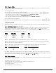
Output Response Curve mA DC Signal Output 20 16 12 8 4 20 0 40 60 80 100 % of Range of Detection Pre-Amp Functional Block Diagram Optical Sensor Temperature Compensation Display Microprocessor 4-20 mA Out I/O Circuit Protection 4-20mA Power In Transmitter Power Supply 3.2 APPLICATION Model IR-540/IR-541/IR-542 MicroSafe™ sensors are designed to detect and monitor CO2 gas in ambient air. Minimum sensitivity and scale resolution is 0.01%. Operating temperature range is -40° F. to +175° F.
Response Time T50 < 15 seconds; T90 < 30 seconds Clearing Time 90% < 30 seconds Repeatability ± 3% FS Range 0 - 0.3/0.5/1/2/3/5% withthe IR-540/IR-541 0-10/0-25/0-50/0-100% with the IR-542 Operating Temperature -40° to +175° F Accuracy ± 5% FS Sensor Warranty 5 year pro-rated Power Consumption Normal operation = 86 mA (2.3 watts); Full alarm = 102 mA (<3 watts) Zero Drift < 0.05% per year Output Linear 4-20 mA DC Input Voltage 11-28 VDC 3.
3.4.3 Program Mode The program mode provides a program status menu, allows for the adjustment of alarm set point levels, and the selection of the calibration gas level setting.. 3.4.3.1 Program Status The program status scrolls through a menu that displays: * The gas type, range of detection and software version number. The menu item appears as: “CO2 RANGE V6.0” * The calibration gas level setting. The menu item appears as: “CalLevel @ #.
Density - Placement of sensors relative to the density of CO2 is such that sensors for the detection of CO2 should be located within 2-4 feet of grade as CO2 will tend to settle in low lying areas. Leak Sources - Most probable leak sources within an industrial process include flanges, valves, and tubing connections of the sealed type where seals may either fail or wear. Other leak sources are best determined by facility engineers with experience in similar processes.
Figure #2 4 3/4" 6 1/8" 5 1/2" 3/4" NPT 3/4" NPT 8 1/4" 1/4" Dia. Mounting Holes Rainshield/ Splashguard 2 1/8" 2" Figure #3 Base Connector Board 4-20 mA Output VDC Power In mA RED BRN WHT BLK YEL BLU Sensor 3.5.6 Remote Mounting Applications Some sensor mounting applications require that the gas sensor head be remotely mounted away from the sensor transmitter. This is usually true in instances where the gas sensor head must be mounted in a location that is difficult to access.
Remote Transmitter IR-540-RT RED BRN WHT BLK YEL BLU Remote Sensor IR-540-RS 56 1234 RED BRN WHT BLK YEL BLU Figure #4 3.6 START UP Upon completion of all mechanical mounting and termination of all field wiring, apply system power and observe the following normal conditions: a) The “Fault” LED is off. b) A reading of 0.00% CO2 should be indicated upon conclusion of a 12 second “warming up” cycle. Note 1: If the display contrast needs adjustment, refer to section 3.10. 3.6.
Magnetic Programming Tool Figure #5 3.6.2 Programming Magnet Operating Instructions Operator interface to MicroSafe™ gas detection products is via magnetic switches located behind the transmitter face plate. DO NOT remove the glass lens cover to calibrate or change programming parameters. Two switches labeled “PGM 1” and “PGM 2” allow for complete calibration and alarm level programming without removing the enclosure cover, thereby eliminating the need for area de-classification or the use of hot permits.
NOTE 1: If the circuitry is unable to adjust the zero to the proper setting the sensor will enter a calibration fault mode which will cause the display to alternate between the sensor’s current status reading and the calibration fault screen which appears as: “CAL FAULT” (see section 3.7.3). NOTE 2: When a “cal fault” occurs, the sensor microprocessor retains its previous calibration references. Zero calibration is complete. 3.7.
3.7.3 Additional Notes 1. Upon entering the calibration menu, the 4-20 mA signal drops to 2 mA and is held at this level until you return to normal operation. 2. If during calibration the sensor circuitry is unable to attain the proper adjustment for zero or span, the sensor will enter into the calibration fault mode which will activate fault alarm functions (see section 3.
Calibration Fault If during calibration the sensor circuitry is unable to attain the proper adjustment for zero or span, the sensor will enter into the calibration fault mode and cause the display to alternate between the sensor’s current status reading and the calibration fault screen which appears as: “CAL FAULT.2”. The following conditions will cause a calibration fault: 1 - Zero calibration cannot converge. 2 - Auto span cannot converge (too noisy or too unstable).
3.11 OPTICAL SENSOR REPLACEMENT PROCEDURE Should the optical gas sensor element (part number 370-365878-111 or 370-287724-232) require replacement, use the following procedure: 1 - (A) If the sensor is mounted in a classified area, system power to the transmitter must first be removed before proceeding further. (B) If in an unclassified area, remove front enclosure cover and unplug transmitter module. 2 - Remove lower half of sensor housing using an alan wrench (3 screws).
Bad 4-20 mA output 1. Check that wiring is connected to correct terminal outputs. 2. Swap with a known-good transmitter to determine if transmitter is faulty Unstable output/Sudden Spiking/Nuisance Alarms 1. Check condulet for accumulated water. 2. Check transmitter and Terminal PCB for abnormal corrosion. 3. Determine if problem correlates with condensation cycles. 4. Add/change Detcon condensation prevention packet. 5. Check for unstable power supply. 6. Check for inadequate grounding. 7.
Programming Magnet Enclosure glass lens cover Plug-in control circuit Rain Shield Spash Guard Calibration Adapter IR Connector Board Enclosure less cover IR Sensor Housing Assembly Condensation Prevention Packet (replace annually) Field replaceable plug-in optical sensor 3.14 WARRANTY Detcon, Inc., as manufacturer, warrants each NDIR optical plug in sensor (part no.
3.16 SOFTWARE FLOW CHART AUTO ZERO LEGEND PGM1 - program switch location #1 PGM2 - program switch location #2 (M) - momentary pass of magnet (3) - 3 second hold of magnet (30) - 30 second hold of magnet INC - increase DEC - decrease # - numeric value AUTO SPAN PGM1 (3) PGM2 (3) CALIBRATION 1-ZERO 2-SPAN PGM1 (3) PGM1 (M) NORMAL OPERATION PGM2 (30) PGM2 (M) VIEW PROG STATUS SET CAL LEVEL PGM1 (3) PGM2 (M) PGM1 (3) PGM2 (M) PGM2 (3) PGM2 (3) LEL 0-100 V#.