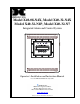
Model X40-08-N4X, Model X40-32-N4X Model X40-32-N1P, Model X40-32-N7 Integrated Alarm and Control System In tegrate d Alarm & C ontrol Sys te m Operator’s Installation and Instruction Manual Covers all Model X40 Control Systems DETCON, Inc. 4055 Technology Forest Blvd., The Woodlands, Texas 77381 Ph.713.559.9200 / Fax 281.298.2868 www.detcon.com January 5, 2015• Document #3672 • Revision 3.
Model X40 This page left intentionally blank Shipping Address: 4055 Technology Forest Blvd., The Woodlands Texas 77381 Mailing Address: P.O. Box 8067, The Woodlands Texas 77387-8067 Phone: 713.559.9200 • Fax: 281.292.2860 • www.detcon.com • sales@detcon.com Model X40 Instruction Manual Rev. 3.
Model X40 Table of Contents 1.0 Introduction........................................................................................................................................1 1.1 1.2 1.3 1.4 1.5 1.6 1.7 1.8 1.9 Features .......................................................................................................................................................... 1 LCD Main Display Function ..................................................................................................
Model X40 6.0 Modbus™ Slave Communications Port.........................................................................................48 6.1 7.0 8.0 Modbus™ Register Map............................................................................................................................... 48 Remote Alarm Reset/Acknowledge Switch Installation ...............................................................50 Troubleshooting Guide..................................................................
Model X40 Figure 24 Model 100 Terminal Board Rotary Switches................................................................................26 Figure 25 N7 AC/DC Converter Board Wiring with Transceiver.................................................................26 Figure 26 N7 DC Power Wiring with Transceiver ........................................................................................27 Figure 27 I/O Module Installation .......................................................................
Model X40 This page left intentionally blank Shipping Address: 4055 Technology Forest Blvd., The Woodlands Texas 77381 Mailing Address: P.O. Box 8067, The Woodlands Texas 77387-8067 Phone: 713.559.9200 • Fax: 281.292.2860 • www.detcon.com • sales@detcon.com Model X40 Instruction Manual Rev. 3.
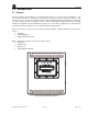
Model X40 1.0 Introduction 1.1 Features The Detcon X40 controller (Figure 1) is a multi-channel gas detection control system. The X40 serves as a host monitor/controller for a network of gas detection sensors and various other field devices. The controller offers a non-intrusive magnetic interface with backlit LCD display and Modbus™ technology that supports either wireless or a hard wire sensor connection.
Model X40 1.2 LCD Main Display Function The main display is an 11/4" x 6" backlit LCD that is four lines by forty characters and displays up to eight configured channels at one time. The four internal magnetic switches are located above the backlit LCD display and offer basic navigation for a complete configuration of the controller (Section 5.1). Real time sensor status includes: channel number gas concentration, device tag (gas type) alarm/fault status.
Model X40 The analog sensors and analog field devices interfaced to the I/O modules communicate with the COMM1 Modbus™ master port on the X40 controller via the I/O Module. Serial sensors interface directly with the COMM1 port and do not require I/O modules. The types of sensors/field devices interfaced will dictate the I/O modules required for the X40 controller. Configuration inputs are completely field-configurable providing a distinctive combination of flexibility and expansion for the customer.
Model X40 Alarm Relay Outputs (RL-4) • Alarms can be used to control (fire) annunciating devices or signal inputs to other control devices. • Four Form C, Single Pole Double Throw (SPDT), 5 Amp relay contacts each assigned specifically to one alarm. • Uses RS-485 Modbus™ RTU protocol to communicate the outputs and must have a unique Modbus™ address set between 80 and 8Fh. • The X40 controller is configured with a maximum of eight separate relay banks each holding up to two RL-4 modules.
Model X40 N7 Enclosure The X40-32-N7 controller is housed in an explosion proof NEMA 7 enclosure for indoor/outdoor use. The N7 enclosure does not accommodate module installations. Modules must be mounted externally by the customer. Any sensors and associated I/O modules will need to be powered separately by the customer. The X40 controller can be powered directly by an external DC source provided by the customer, which meets the input requirements (11.5-30VDC) of the unit.
Model X40 Non-Silenceable The corresponding alarm LED and relay will remain activated until the cause of the alarm or fault is clear. Latching Mode The relay can be deactivated after the alarm condition has cleared by acknowledging the Alarm Reset function on the front panel of the X40 controller or by activating the external reset switch if installed (Section 7.0). Non-Latching Mode The relay is deactivated as soon as the sensor alarm or fault condition is clear. 1.
Model X40 1.9 Operator Interface Reference the Menu Flow Chart (Figure 2) to learn how to easily navigate the menus and make changes.
Model X40 1.9.1 Magnetic Programming Tool The magnetic programming tool (Figure 3) is used to operate the magnetic switches. For switch activation, the programming magnet is briefly held on the switch marker () and then removed. This action will be referred to as a "swipe" for the remainder of this manual. Figure 3 Magnetic Programming Tool 1.9.2 Front Panel User Interface The front panel user interface (Figure 4) contains four switches necessary to configure the X40 controller.
Model X40 The ENTER function is used to accept selections in all menu screens and to execute the Reset and Acknowledge functions. The Reset function releases all latched relays once the alarm/fault condition has cleared. The Acknowledge function will disengage any silenceable relays that are in an active state. This is used to silence alarms once the end-user has assessed the alarm condition.
Model X40 1.10.3 RL4/Alarm Stations Group Hardwired RL4 Module RMXX> ‘Status’ XX – represents the RL4 Modbus slave address. ‘Status’ – Status message of the RL4 module. COMM ERR = Not communicating with module. RL4 MODULE = Communicating with module. Wireless Alarm Stations ASXX ‘Status’ YYY% XX – represents the alarm station Modbus slave address. ‘Status’ – Status message of the alarm station. OFFLINE = Not communicating. DC POWER = Communicating; line powered.
Model X40 Set Channel Alarms All sensors have three alarm settings ALM1 (Alarm 1), ALM2 (Alarm 2) and ALM3 (Alarm 3). The user establishes the alarm levels for each sensor depending on the range. The values represent the alarm level set points and entered in 5% increments of the full-scale range selected for that channel. In ascending mode the relay is activated when the concentration is above the alarm threshold.
Model X40 1.13 Wireless Option The Model X40 controller offers a wireless option that uses Modbus™ technology to connect the controller and other devices to a wireless platform. The local Modbus™ communication uses a wireless grid of transceivers to broadcast information throughout the wireless network, creating a seamless network of Modbus™ devices that are not physically connected. The transceiver operates at 2.4GHz and conforms to non-licensed radio frequency usage worldwide.
Model X40 2.0 Installation 2.1 Safety Guidelines If equipment is used in a manner not specified by Detcon, the protection provided by the equipment may be impaired. CAUTION The user must consult this manual for more information about any location marked with this symbol. DANGER Danger of electrical shock. User must ensure that power has been disconnected prior to installation or servicing of the equipment.
Model X40 Figure 6 N1P Controller Mounting and Dimensional View 19" 1.7" 12" 7.5" 18.25" 5.75" 8.7" 6.94" 0.375" R0.109" Slot Detail 0.218" Figure 7 N1R Controller Mounting and Dimensional View NOTE If the AC and DC wiring are run in conduit, ensure that the AC wiring is not housed in the same conduit as the DC signal/wiring NOTE The power supply for the X40-32-N1P and X40-32-N1R is capable of handling AC inputs between 100-120/220-240VAC, 50-60Hz without degradation. 3.
Model X40 A B RS-485 VDC RS-485 Out SLAVE RESET + A B DC Comm 24VDC Disconnect Terminal Blocks Figure 8 N1P and N1R Connections 5. If 24VDC is required to power external sensors, connect the sensors to the power terminals labeled VDC Out, ‘+’ and ‘–‘. 6. If linking the X40 enclosure to an RD-64X remote display unit, connect the unit to the terminals labeled RS-485 Slave: ‘A’, ‘B’, and ‘Shld’. Model X40 Instruction Manual Rev. 3.
Model X40 2.3 N4X Enclosure Installation The power supply for the X40-08-N4X controller can power a maximum of eight sensors even though the controller is capable of communicating with 32 devices. An additional power supply will be required if powering more than eight sensors or an upgrade to Model X40-32-N4X is needed which can power CAUTION a maximum of 32 sensors. Damage to the power supply may result if the maximum number of sensors is exceeded.
Model X40 16" 12" Ø0.31" 8.80" 8.5" Mounting Bracket 16.75" 17.85" Figure 10 X40-32-N4X Controller Mounting and Dimensional View NOTE If the AC and DC wiring are run in conduit, ensure that the AC wiring is not housed in the same conduit as the DC signal/wiring NOTE The internal power supply in the X40-08-N4X and X40-32-N4X converts 100-120/220240VAC to 24VDC. Up to 2A @ 24VDC is available to power sensors attached to the X40.
Model X40 Circuit Ground Conductor Lock Washer (Toothed if on Paint) Protective Earth Conductor from Main Chassis Figure 11 N4X Protective Earth Connector A1, B1 are Master RS-485 Port Drop-In Display Assembly A2, B2 are Slave RS-485 Port PWR GND A2 B2 A1 B1 SW SW PCA Connector Figure 12 Display Wiring Bottom View of Enclosure AC Cable Entry Point Drill Hole in Area for AC Cable Access Drill Hole in Area for Sensor, Relay Cable Access Figure 13 Cable Entry Points 3.
Model X40 at the unit when needed. CAUTION Equipment and equipment to be electrically connected shall use safety approved wire/cable in conjunction with appropriate and compatible protective cable gland, all of which meet the requirements of the max equipment rating (250VAC, 5A) and any local electrical codes, regulations and standards. The cable used to connect to the terminals of the X40-32-N4X must be rated for a minimum of 105ºC. 5. Install the DC power as follows: a.
Model X40 A B 8. If linking the X40 enclosure to an RD-64X remote display unit, connect the unit to the slave port terminals labeled RS-485 Slave: ‘A’, ‘B’, and ‘Shld’ (Figure 16). RS-485 SLAVE Figure 16 N4X RS-485 Slave Port Connections 9. If the X40-N4X was ordered with the wireless option, the radio module is installed in the enclosure and an antenna connector is provided on the top of the enclosure (Figure 17).
Model X40 2.4 N7 Enclosure Installation The X40-32-N7 controller can support up to a maximum of 32 sensors and any associated I/O modules, but no I/O modules can be installed in the controller. All I/O modules must be mounted separately by the customer. The N7 version does not supply power to sensors. Power must be supplied by the customer for sensors and any I/O modules. Damage to the controller may result if the maximum number of sensors is exceeded. CAUTION 1.
Model X40 1 SW4 SW3 SW2 SW1 R8 J5 J7 1 PWR J7 D3 D4 D5 D6 MAIN GND PWR A2 GND J2 SECONDARY 1 A2 B2 B2 A1 B1 A1 SW J6 B1 SW Figure 19 N7 Controller PCA CAUTION The cable used to connect to the terminals of the X40-32-N7 must be rated for a minimum of 105ºC. 4. If the unit comes with the optional mounting plate and a Condulet, attach the mounting plate assembly to a pole with two U-Bolts secured through the 7/16" rectangle holes of the mounting plate base (Figure 20).
Model X40 NOTE Proper electrical installation of the wireless radio module assembly is critical for conformance to Electrical Codes and to avoid damage due to water leakage. A conduit seal is typically required to be located within 18" of the transceiver assembly if a conduit run is required. Crouse Hinds type EYS2, EYD2 or equivalent are suitable for this purpose. NOTE Any unused ports should be blocked with suitable 3/4" male NPT plugs.
Model X40 b. J1 should come wired and connected to the controller from the factory. Ensure that J1 is properly connected to the AC/DC Converter. c. Interface the I/O modules and sensors to the X40 controller through the J2 connector of the AC/DC converter board (Figure 21). NOTE The terminals on the J3 connector are labeled N (neutral), L (line power) and E (earth ground). NOTE An optional Transient Protection board is available from Detcon for use with external DC Supply.
Model X40 Pole U-bolts Figure 23 Typical NEMA7 with Transceiver Table 1 X40 Model 100 Terminal Board Connector Plugs J1 4-Pin Connector Modbus™ Out (Wireless Transceiver Option) J2 6-Pin Header Wireless Transceiver Programming Header J3 6-Beau Connector Battery operation or display interface dependent on sensor configuration J4 4-Pin Connector Modbus™ In – Connects to X40 J5 Not used J6 Not used J7 4-Pin Connector Connection to solar panel J8 6-Pin Connector Wireless Transceiver J9
Model X40 3. Ensure that the two rotary switches on the Model 100 Terminal Board are set to the Modbus™ address (F0h) for the wireless radio module of the X40 controller. The Model 100 Terminal Board should come set from the Detcon factory and should be set to the address to F0h. Access the terminal board and locate the switches shown in Figure 25.
Model X40 CAUTION The cable used to connect to the terminals of the X40-32-N7 must be rated for a minimum of 105ºC. 2. Install AC power and I/O connections when the N7 is supplied with a J-Box and an AC/DC converter. Connect 100-240VAC input wiring to the J3 connector (labeled AC IN) of the converter board. NOTE The terminals on the J3 connector are labeled N (neutral), L (line power) and E (earth ground).
Model X40 3.0 I/O Connections 3.1 I/O Module Installation Module installation limits are as follows: • A maximum of two I/O modules may be installed on the N1P enclosure. • The quantity of I/O modules supported by the X40 NEMA 4 enclosures is dependent on the configuration of the controller. • The X40-32-N7 enclosure does not accommodate module installations. NOTE Modules for the N7 enclosure or any additional modules for the other enclosure types must be mounted in a separate enclosure by the customer.
Model X40 3.2 Analog 4-20mA Sensor Inputs (DA-4) Connect the 4-20mA gas sensors to DA-4 4-20mA input modules. The DA-4 modules provide power to any 2-wire or 3-wire field sensors, and receive standard 4-20mA signal inputs from the sensors Figure 29. NOTE The terminals on the DA-4 module are rated for a maximum of 30VDC. They are designed to accept solid or stranded wire between 12AWG and 24AWG. NOTE Analog sensors used with the X40 must supply 4mA for a zero reading and 20mA for a full scale reading.
Model X40 Sensor 4 Sensor 3 COMM M S D L S D 4-20mA INPUT Sensor 1 Sensor 2 Figure 30 Model DA-4 4-20mA Input Module and 4-20mA Gas Sensors Serially address each DA-4 module in hex using the two rotary switches on the front of the module labeled MSD (most significant digit) and LSD (least significant digit). Ensure that each DA-4 module has a unique Modbus™ address and is addressed within the range 01h-7Fh.
Model X40 4mA Reading NO NC Input 4 mA + Input 3 mA + There are four relay contact inputs on each DI-4 module. COM Relay Contacts COMM M S D L S D CONTACT INPUT Input 1 Input 2 + mA + mA 20mA Reading NO NC COM Relay Contacts Figure 31 Model DI-4 Contact Input Module NOTE The terminals on the DI-4 module are rated for a maximum of 30VDC. They are designed to accept solid or stranded wire between 12AWG and 24AWG.
Model X40 4-20 mA Signal Output 4 mA _ Output 3 mA _ There are four 4-20mA outputs on each AO-4 module. 4-20mA Input Control System COMM M S D L S D 4-20mA Output Output 1 _ mA Output 2 _ mA Figure 32 Model AO-4 4-20mA Output Module NOTE The terminals on the AO-4 module are rated for a maximum of 30VDC. They are designed to accept solid or stranded wire between 12AWG and 24AWG.
Model X40 Module 4 NOTE Channel # 13 14 15 16 Decimal Hex Module 164 A4 8 Channel # 29 30 31 32 Decimal Hex 168 A8 The AO-4 modules must be connected to the RS-485 Master Port and addressed correctly in the range of A1h-A8h. An AO-4 module connected properly to the controller will have a flashing DATA COMM LED to indicate a valid communication status and will provide a continuous output mA reading that corresponds directly to the sensor attached.
Model X40 NOTE External devices attached to the RL4 outputs must require a tool to access their wiring terminals to prevent unauthorized access. NOTE Hazardous live voltages of external devices attached to the equipment must be isolated or disconnected prior to accessing the terminals of the external devices NOTE The cable penetration for the relay outputs must be made in the bottom of the enclosure (See Figure 13).
Model X40 RS-485 VDC Out The only Modbus™ capable Detcon sensors that may be used with the X40 are Model 100, Model 600 and Model 700 series. + NOTE B A Figure 34 Modbus™ Gas Sensor Connections NOTE Each sensor and DIN rail module must have a unique Modbus™ address. No two devices on the Modbus™ network can have the same address. Ensure that each serial sensor is assigned a unique Modbus™ address and within the range 01h-7Fh.
Model X40 Modbus at the Modbus address assigned to the transceiver enabling analog inputs to be configured automatically with the Auto Configure function of the MCX-32. The two 4-20mA inputs are accessible when an RXT-320 transceiver is connected to Detcon’s optional Model 100 Terminal Board. ‘AIN1’ on connector J8 corresponds to analog input one and ‘AIN2’ on connecter J7 corresponds to analog input two.
Model X40 RF Channel Modbus Address SW1 SW3 LSD SW2 MSD Figure 36 CX/CXT Wireless Transceiver The CXT Slave Controller has the option of employing a Relay Output PCA. The relay output PCA of the CXT Slave Controller is controlled by the CXT Slave Controller, and is not, and should not be considered as part of the X40 Alarms. The X40 has no control over the CXT Slave Controller‘s relay output PCA.
Model X40 The 4-20mA signals from the sensors are communicated by the CXT Slave Controller to the X40 controller using RS-485 Modbus™ RTU protocol. The analog input PCA is serially addressed to the CXT Slave Controller in hex using the two rotary switches labeled SW2 MSD (most significant digit) and SW1 LSD (least significant digit). The analog input PCA should have an address of 01h to interface properly with the CXT Slave Controller.
Model X40 3.11 General Installation Wiring Notes Follow generally accepted guidelines for RS-485 serial networks. Do not wire I/O Modules and/or Modbus™ gas sensors in long-distance ‘T-Tap’ configurations. Instead, use a “daisy-chain” wiring scheme. Use Detcon Recommended cabling whenever possible. General Cable Commodore P/N ZO16P0022189 is recommended for a single cable providing serial communications and power. Ground the cable shielding at the Model MCX-32 controller only.
Model X40 4.0 Secure Digital Card NOTE Ensure that power is turned off to the X40 before installing or removing the SD card. 1. Install the SD card in the SD slot (J9) on the back of the controllerꞌs PCA before the controller is powered up. 2. The controller will notify the user if a successful installation of the card was achieved upon power up. 3. The controller will automatically format the card and create the necessary files for data logging. Refer to Section 5.2.
Model X40 5.0 System Configuration 5.1 X40 Controller Setup 1. The PROG switch is used to enter the menu mode of the unit by swiping a programming magnet over the corresponding marker (). Upon entering the menus, all Modbus™ polling stops, sensor values are not read and alarm outputs are not updated. NOTE If the X40 is in alarm when the user enters the menu, it will stay in alarm until they exit the menu. 2.
Model X40 4. Swipe the ENTER marker to initiate the search. The X40 controller will perform an incremental search for available 700/100 and 600 serial sensors starting with Modbus™ address 01h and analog inputs with a minimum current of 1.80mA. NOTE All sensors and modules must be powered on to be detected correctly. NOTE The channel tags for the analog inputs will be set to "PPM H2S" by default. These can be changed in the Utilities menu.
Model X40 The ENTER marker will save the selected value and return to the flashing cursor. 3. If there is more than one channel, a swipe of the down arrow marker while the flashing cursor is on RL4 BANK CNT will scroll the display to the next channel allowing for its configuration. To return to the previous channel, a swipe of the up arrow marker should be performed while the flashing cursor is on SLAVE ID. 4.
Model X40 The ENTER marker will select the function indicated by the flashing cursor The markers of the up or down arrows will change the value. The ENTER marker will save the selected value and return to the flashing cursor. 3. If there is more than one channel, a swipe of the down arrow marker while the flashing cursor is on ALM3 ASCENDING will scroll the display to the next channel allowing for its configuration.
Model X40 Silenceable or Non-Silenceable NOTE It is generally recommended to set the FAULT relay as energized so that it will trip upon loss of power. NOTE The FAULT condition is assigned to the FAULT relay as a standard. It cannot be disengaged in the configuration of the controller. The Main Display will show IN FAULT for any channel that is in fault. 5.2.5 Inhibit and Alarm Test Mode Inhibit mode permits testing of sensors while preventing alarms from being activated.
Model X40 LEDꞌs. After the LED test, the controller initiates a test for the external reset switch which lets the user know when the reset switch is pressed. The user will be prompted: 1. To "press (swipe) enter key (marker) to continue" which will initiate the relay driver test and the controller will then reset all the relays and turn on the alarm 1 relay. 2. To "press (swipe) any key (marker)" which will turn on the alarm 2 relay. 3. To "press any key" and the alarm 3 relay will be turned on. 4.
Model X40 10. A swipe over the ENTER marker will select the field indicated by the arrow prompt and the value can be changed by swiping over the markers of the up or down arrows. 11. Another swipe over the ENTER marker will save the selected value. 12. Once the desired values have been set, move the arrow prompt to "Change Date" and swipe the ENTER marker to update the date with the changes entered. 13.
Model X40 6.0 Modbus™ Slave Communications Port A Modbus™ RTU master can poll the slave port on the X40 allowing the Modbus master to remotely monitor the status of the X40. If multiple X40s are being used on a single Modbus™ network, each controller must be set to a different device address. 6.
Model X40 Reading Register Current gas reading of the channel assigned to the register.
Model X40 7.0 Remote Alarm Reset/Acknowledge Switch Installation 1. Mount the reset switch on the bottom or side of the NEMA 4X enclosure. For the other enclosure types, the switch must be mounted externally such as in the bottom of a J-Box. 2. Standard Momentary Pushbutton Switch a. The standard reset switch should be a Normally Open, Momentary Closed switch that is rated for the area of installation. b.
Model X40 8.0 Troubleshooting Guide Unit will not power up Verify correct AC or DC voltage selection. Verify correct VAC and VDC powering configuration. Relays are not firing Verify that the alarm relays are configured properly. Alarms on constantly Ensure that no channels are set to ascending or descending incorrectly. Alarm Firing causes unit to "Lock Up" Verify that the alarm annunciator current draw does not exceed the on-board power supply limits. Replace with external power supply if necessary.
Model X40 8.2 Replacement of the NEMA 4 Drop-In Display Assembly The NEMA4 enclosures come with a ‘Drop-In’ Display Assembly (P/N 949-005142-200) 1. Unplug the connector from J7 on the Display Assembly. 2. Remove the 10 Hex-Head bolts holding the Display Assembly to the cover of the enclosure 3. Replace the Drop-In Display Assembly on the enclosure cover, and replace the 10 Hex-Head Bolts. 4. Ensure that gasket is placed between the Drop-In Display Assembly and the cover. 5.
Model X40 9.0 Customer Support and Service Policy Detcon Headquarters Shipping Address: 4055 Technology Forest Blvd, The Woodlands, Texas 77381 Mailing Address: P.O. Box 8067, The Woodlands Texas 77387-8067 Phone: 713.559.9200 Fax: 281.298.2868 • www.detcon.com • service@detcon.com • sales@detcon.com All Technical Service and Repair activities should be handled by the Detcon Service Department via phone, fax or email (contact information given above).
Model X40 10.0 Warranty Notice Detcon Inc. warrants the X-40 Integrated Alarm and Control System to be free from defects in workmanship of material under normal use and service for two years from the date of shipment on the transceiver electronics. Detcon Inc. will repair or replace without charge any such equipment found to be defective during the warranty period. Full determination of the nature of, and responsibility for, defective or damaged equipment will be made by Detcon Inc. personnel.
Model X40 11.0 Appendix 11.
Model X40 11.
Model X40 11.3 Utilities Contact a Detcon representative prior to changing any settings in this section. Default settings are functional for the majority of applications. Any adjustments made to other items may cause the controller or various components to not work properly. CAUTION X40 controller setup is accomplished through the Main Menu and consists of 9 menu items: 1. Setup Channel Data 2. Set RF Silence and RF Sleep 3. Set Low Battery Alarms 4. Set Modbus Address 5. CXT Low Battery Threshold 6.
Model X40 Device Type Value The Device Type values available are 100, 700, 600 (Detcon serial sensor models), DA4/DI4 (analog sensors) or radio module (when analog inputs are in use). Ensure that the appropriate value corresponding to the sensor or device is assigned to the indicated channel. Analog Input Value The Analog Input is only available for analog sensors and devices. Analog sensors (DA4/DI4), the available value is 1, 2, 3 or 4 corresponding to the input position on the DA-4/DI-4 module.
Model X40 11.3.2 Set RF Silence and RF Sleep (Wireless Function Only) The Set RF Silence and RF Sleep menu allows the user to initiate radio silence for a predetermined amount of time, over the entire network. RF Sleep terminates communication (sleep command) between all of the wireless radio modules in the network as a power saving feature. A longer sleep time will increase delay between alarm conditions occurring and the alarms being activated.
Model X40 recommended value should be 25%. The blue LED on the controller will be activated and begin flashing when any battery in the network falls below the set thresholds. 11.3.4 Set Modbus™ Address The SET Modbus™ Address menu establishes the serial address of the X-40 controller when being polled by another master device through the RS-485 Modbus™ RTU slave port (COMM2). 1. Upon entering this menu, the LCD will display: MODBUS ADDRESS: ### 2.
Model X40 The Set COMM Baud Rates menu displays the current baud rate settings for COMM1 (master) and COMM2 (slave). Upon entering this menu, the LCD will display: SET COMM BAUD RATES: COMM1 BAUD RATE:9600 COMM2 BAUD RATE:9600 NOTE The value shown is pre-configured to 9600 and should not be altered unless directed to do so by Detcon factory personnel. 11.3.8 Set Modbus™ Timeouts The Set Modbus™ Timeouts menu establishes the response timeout for Modbus™ communications and the inter-poll delay.
Model X40 2. These values can be changed by swiping the magnet over the markers of the up or down arrows to move the arrow prompt "→" to the desired function. A swipe over: The ENTER marker will select the function indicated by the arrow prompt "→". The markers of the up or down arrows will change the value. The ENTER marker will save the selected value. Model X40 Instruction Manual Rev. 3.
Model X40 11.4 Spare Parts and Wireless Accessories Part Number 360-ML1000-024 975-041402-000 976-041400-000 975-041401-000 975-041400-000 327-000000-000 500-003087-100 500-005156-000 500-005142-100 500-005142-200 949-005142-200 Part Number 976-00132D-000 976-0003A4-200 976-000320-316 500-005168-100 897-850000-010 897-850901-010 897-850902-010 960-202200-000 8522-750 899-07550 899-150750-316 301-58205 Model X40 Instruction Manual Spare Parts Power Supply 4.
Model X40 11.5 Revision Log Revision 0.0 0.1 Date 02/07/2011 03/18/2011 1.0 07/29/2011 1.1 08/10/2011 2.0 2.1 2.2 3.0 3.1 3.2 3.3 3.4 11/14/11 04/02/12 07/10/12 12/07/12 09/10/13 11/22/13 05/16/14 01/05/15 Model X40 Instruction Manual Changes made Initial Release. Corrected AO-4 modbus address range. Corrected enclosure dimensions for 32 channel enclosure and added drawing for 8 channel enclosure. Revised DC input voltage specs.
Model X40 This page left intentionally blank Model X40 Instruction Manual Shipping Address: 4055 Technology Forest Blvd., The Woodlands Texas 77381 Mailing Address: P.O. Box 8067, The Woodlands Texas 77387-8067 Phone: 713.559.9200 • Fax: 281.292.2860 • www.detcon.com • sales@detcon.com Rev. 3.