Model MCX-32-N1P Model MCX-32-N4X Gas Detection Controller Operator’s Installation and Instruction Manual Covers all Model MCX-32 Control Systems DETCON, Inc. 4055 Technology Forest Blvd., The Woodlands, Texas 77381 Ph.281.367.4100 / Fax 281.298.2868 www.detcon.com February 15, 2013 • Document #3624 • Revision 2.
Model MCX-32 This page left intentionally blank Model MCX-32 Instruction Manual ii
Model MCX-32 Table of Contents 1.0 Introduction ........................................................................................................................................ 1 1.1 Description ...................................................................................................................................... 1 1.2 System Operation ............................................................................................................................ 1 1.2.1 Interface PCA ...
Model MCX-32 6.3.9 Power Management Screen ....................................................................................................26 6.3.10 Display Settings Screen ..........................................................................................................28 6.3.11 Restore Defaults .....................................................................................................................28 6.3.12 Compact Flash Screen......................................................
Model MCX-32 Figure 24 Modbus Utilities...........................................................................................................................25 Figure 25 Device Modbus Diagnostics Screen..............................................................................................25 Figure 26 Alarm Inhibit Screen ....................................................................................................................26 Figure 27 Power Management Screen .......................
Model MCX-32 This page left intentionally blank Shipping Address: 4055 Technology Forest Blvd., The Woodlands Texas 77381 Mailing Address: P.O. Box 8067, The Woodlands Texas 77387-8067 Phone: 888.367.4286, 281.367.4100 • Fax: 281.292.2860 • www.detcon.com • sales@detcon.
Model MCX-32 1.0 Introduction 1.1 Description The Detcon Model MCX-32 is a multi-channel gas detection controller designed to serve as a host monitor and controller for a network of gas detection sensors as well as a wide range of other field devices. All MCX-32 models are configurable for up to 64 channels and can communicate with serial sensors directly via RS-485 Modbus™ and analog sensors using Detcon’s selection of I/O modules.
Model MCX-32 The number of I/O modules supported by the MCX-32 controller will vary depending on the enclosure type chosen due to physical space limitations. A maximum of 2 I/O modules will fit outside the MCX-32-N1P enclosure and a maximum of 16 I/O modules will fit inside the MCX-32-N4X enclosure. I/O modules are normally factory installed unless specifically instructed otherwise. Any additional modules will have to be mounted in a separate enclosure by the customer. I/O modules are purchased separately.
Model MCX-32 1.2.3 Auxiliary Relays The Interface PCA contains two relays that can be configured and used for contact closure outputs for ‘FAULT’ and ‘NO-COMM’ errors. The Fault Relay is set whenever there is a sensor fault, and the No-Comm relay is set when there is a no communication error. These relays are configurable as to how they will be set when a fault or no communication error occurs. The relays may be configured as Energized or De-energized, Silence or Non Silence, and Latched or Unlatched.
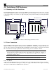
Model MCX-32 2.0 Installation (N1P Enclosure) 2.1 Mounting and Cable Installation The Model MCX-32-N1P controller is housed in a NEMA 1 panel mount enclosure for indoor use. Securely mount the Model MCX-32-N1P per the mounting dimensions provided in Figure 1. The enclosure is designed to fit a panel opening of 9.25” wide by 7.5” high. Keep AC power separate from DC power and signals within conduit runs. Allow at least 13" of Clearance for wiring 8" 10.5" 9.75" HOME ALARM RESET 3.
I ON I ON WMS1C03 240V10000 WMS1C03 240V10000 WMS1C03 240V10000 24VDC NEU (L2) I ON C3A C3A C3A Model MCX-32 VAC (L1) GROUND Figure 2 AC/DC Inputs NOTE: The input voltage range must be between 110-240VAC. 2.2.2 DC Power For optional external DC power input, connect 20-30VDC to the terminals located on the back of the enclosure, labeled “24VDC” and “DC Comm” (See Figure 2). This input can be used for primary power or back-up power in the event of an AC power failure.
Model MCX-32 3.2 Power Connections The Model MCX-32-N4X controller can be powered by 110/220VAC, 20-30VDC or both. An internal power supply is available for the MCX-32-N4X that converts 110/220VAC to 24VDC (up to 5Amps) and can power up to 32 sensors and any associated I/O modules. The MCX-32 controller can also be powered by an external DC source that meets the input requirements of the unit if AC power is not available or desired.
B A RS-485 VDC PORT2 Out + B A + B A RS-485 VDC RS-485 PORT1 Out Model MCX-32 Figure 4 RS-485 Wiring Terminals for PORT1, PORT2 and REMOTE WARNING: Do not attach more devices to the controller power supply than the power supply has the capacity for, as damage may occur to the controller and will void the warranty. The capacity is 3Amps maximum. Modules and sensors attached to the controller that exceed this rating should be powered by an external power supply capable of handling the extended load.
Model MCX-32 Sensor 4 Sensor 3 COMM M S D L S D 4-20mA INPUT Sensor 1 Sensor 2 Figure 6 Model DA-4 4-20mA Input Module and 4-20mA Gas Sensors Table 1 DA-4/DI-4 Modbus Addresses Port Module 1 3 1 5 7 9 11 2 13 15 Channel # 1 2 3 4 9 10 11 12 17 18 19 20 25 26 27 28 33 34 35 36 41 42 43 44 49 50 51 52 57 58 59 60 Model MCX-32 Instruction Manual Decimal Hex Module 64 40 2 66 42 4 68 44 6 70 46 8 72 48 10 74 4A 12 76 4C 14 78 4E 16 Rev.2.
Model MCX-32 The 4-20mA signals from the sensors are communicated by the DA-4 modules to the controller using RS-485 Modbus™ RTU protocol therefore each DA-4 module must have a unique Modbus™ address. Modules are serially addressed in hex using the two rotary switches on the module’s front panel labeled MSD (most significant digit) and LSD (least significant digit). The DA-4 modules must be addressed according to Table 1 DA-4/DI-4 Modbus Addresses.
Model MCX-32 The state of the contact outputs from field devices are communicated by the DI-4 modules to the controller using RS-485 Modbus™ RTU protocol therefore each DI-4 module must have a unique Modbus™ address. Modules are serially addressed in hex using the two rotary switches on the module’s front panel labeled MSD (most significant digit) and LSD (least significant digit). The DI-4 modules must be addressed according to Table 1 DA-4/DI-4 Modbus Addresses.
Model MCX-32 As an example, assume all 64 channels from the MCX-32 have sensors configured to them and the sensor reading of channel 39 is wanted as an input to another control device. First note that channel 39 corresponds to module 10 in Port 2 with hex address A9 per Table 2. Therefore, an AO-4 module set to hex address A9 would need to be installed in Port 2 of the MCX-32. Next, the ‘Analog Out’ on the Channel Details screen for channel 39 would need to be turned ‘ON’.
Model MCX-32 Details screen. After identifying the correct port and address for the AO-4 module, the ‘Analog Out’ must be turned ‘ON’ from the Channel Details screen for the specific channel corresponding to the AO-4’s output. A properly addressed AO-4 that is correctly connected and configured to the controller will respond to channel activation with a 4-20mA output reading equal to the current concentration reading reported to the controller for the associated channel. 4.
Model MCX-32 The MCX-32 controller has been configured to have three separate relay banks (Bank1, Bank2 and Bank3). Each bank can hold up to five RL-4 modules and are defined by addresses 80h-84h for Bank1, 85h-89h for Bank2 and 8Ah-8Eh for Bank3. Anytime a specific alarm is fired for a module in a bank, all corresponding alarms for all modules in that particular bank are also triggered.
Model MCX-32 the corresponding relay, once activated, can be deactivated by pressing the Alarm Silence button on the left edge of the screen. 4.4.3 Latching or Non-Latching Relays All alarms - Alarm 1, Alarm 2, Alarm 3, and Fault - can be configured as either latching or non-latching. In non-latching mode, the relay is deactivated as soon as the sensor alarm (alarm relays) or fault (fault relay) condition is cleared.
Model MCX-32 4.6 Serial Output Gas Sensors (RS-485) Serial output gas sensors can be interfaced directly to the MCX-32 controller without the need for I/O modules. This is accomplished by connecting the sensors in series to the controller’s Port 1 or Port 2 Modbus™ interface. Each serial sensor must have a unique Modbus™ address and be connected to the correct port for the controller to communicate properly.
Model MCX-32 labeled NO1, C1, and NC1 for the NO-COMM relay, and NO2, C2, and NC2 for the FAULT relay. (NO – Normally open Contact, C – Common Contact, and NC – Normally Closed Contact.) These relays may be setup as Energized or De-energized, Silence or Non Silence, and Latched or Unlatched, refer to section 6.3.2 RL4 Setup Screen for the configuration of the relays. FAULT PORT 1 PORT 2 NO-COMM PORT 3 PORT 4 PORT 5 Figure 12 Interface PCA 4.
Model MCX-32 files for data logging. Data is recorded onto these files which can then be viewed from the controller’s Compact Flash screen at the user’s convenience. The CF card can also save the controller’s current configuration and be used to load its saved configuration to other MCX-32 controllers. See section 6.3.12 for more information regarding the data logging feature and Compact Flash screen.
Model MCX-32 Figure 14 Model MCX-32 Main Display Screen Along the side of the display are a group of navigation and action buttons labeled: ‘HOME’, ‘ALARM RESET’, ‘ALARM SILENCE’, ‘ALARM INHIBIT’, and ‘MENU’. These buttons perform different tasks when pressed: HOME – Return to the Main screen. This button will return the display to the Main screen from any other screen. ALARM RESET – When latched alarms have occurred, will reset all latched alarm notifications.
Model MCX-32 Figure 15 Channel Details Screen The Channel Details screen is used to view or change information directly related to a sensor. The Channel Details screen displays the sensor’s description, the current reading, the gas type & units, the channel’s on/off status, the life of the sensor, the range of the sensor, the analog output status, the device type, the sensor status, the alarm values and the bank(s) the alarms are associated with. Refer to Section 7.
Model MCX-32 NOTE: The COMPACT FLASH menu button only appears if a CompactFlash card has been successfully installed in the MCX-32 controller. The System Configuration screen provides access to twelve different menus that allow the user to change the controller’s configuration.
Model MCX-32 located at the bottom of the screen, the controller will save the current configuration of all devices found up to that point, overwriting any previous configuration. Figure 17 Auto Configure System Screen NOTE: The Auto Configure System operation does not recognize DA-4 or DI-4 modules. Sensors connected to the controller using DA-4 or DI-4 I/O modules must be manually configured to the controller. 6.3.2 RL4 Setup Screen The RL-4 Setup screen is displayed when RL4 SETUP is selected.
Model MCX-32 Figure 18 RL-4 Setup Screen Each RL-4 module consists of four relays. To configure these relays, select the ‘RELAY CONFIG’ button at the bottom of the RL4 Setup screen. All four relays will be displayed for each bank. Selecting the ‘RL4 SETUP’ button will return to the RL4 Setup screen, and selecting ‘NEXT BANK’ will go to the next bank, selecting ‘PREV BANK’ will go to the previous bank, where the same parameters can be set for that bank.
Model MCX-32 and NC – Normally Closed Contact.) These relays may be setup as Energized or De-energized, Silence or Non Silence, and Latched or Unlatched by selecting the ‘AUX RLY CONFIG’ button located at the bottom of the RL4 Modules screen. 6.3.3 Change Password Screen The Change Password screen allows the user to change the password required to log in to the MCX-32 controller. When selected, the user is prompted to enter ‘Current Password’, ‘New Password’, and ‘Re-Type New Password’.
Model MCX-32 6.3.5 Alarm Test Mode When selected, ALARM TEST MODE menu button will simulate alarm conditions by incrementing the gas readings from 0 for all active gas channels at 5% full scale. Once the concentration has reached full scale, the concentration will begin to decrement back to 0 and the controller will exit the test mode. The test mode can also be terminated at any time during the test cycle by selecting the ALARM TEST MODE menu button again.
Model MCX-32 6.3.7 Modbus Utilities Screen The Modbus Utilities screen provides the ability to check the status of all Modbus™ addresses for the MCX32 controller which includes all 64 channel addresses, all 15 RL-4 addresses and all 16 AO-4 addresses. The information displayed consists of the Modbus Address, Status, COMM Error Count and COMM Error Total Time.
Model MCX-32 6.3.8 Alarm Inhibit Screen The Alarm Inhibit screen allows the user to inhibit alarms for a pre-determined amount of time. The screen is identified as ‘ALARM INHIBIT’. The screen is typically used to inhibit alarms during calibration of a sensor. When logged in, selecting the ‘INHIBIT TIME’ field will open a numeric keypad used to enter the length of time the controller will inhibit alarms. When the amount of time has been entered, select the ‘START’ button to start the time counter.
Model MCX-32 Figure 27 Power Management Screen The controller has the unique ability to provide a charging voltage for batteries. If batteries are connected to the auxiliary 24VDC input, this feature will provide a nominal 27VDC @ 1Amp (maximum) to the auxiliary 24VDC input to charge the batteries. The circuit will monitor the batteries and keep the batteries at full charge.
Model MCX-32 6.3.10 Display Settings Screen The Display Settings screen allows the adjustment of the screen brightness and contrast, the calibration of the screen touch panel, and the setting of the time and date. Figure 29 Display Settings 6.3.11 Restore Defaults When selected, this button will restore default values to all of the channel’s alarm set points. This will not affect the channel description or other parameters pertaining to each channel. 6.3.
Model MCX-32 user can also page back and forth to different dates by selecting the buttons on the bottom of the screen labeled ‘PREV DAY’ and ‘NEXT DAY’. Figure 31 TWA & PEAK Screen Selecting the VIEW EVENTS button displays the EVENTS screen (Figure 32) which allows the user to view recorded events such as alarms, faults, comm errors, alarm inhibits, etc.
Model MCX-32 stored in these logging files. When selected, a warning window will be displayed (Figure 33) prompting the user to confirm the reset of the CF card. Selecting the ‘YES’ button will erase all the data recorded up to this point and initiate the recording of new data. Selecting the ‘NO’ button will cancel the reset and no data will be deleted from the logging files. Figure 33 Format CompactFlash Warning Window NOTE: Do not remove or insert the CompactFlash card while power is applied.
Model MCX-32 the channel is on or off, the life of the sensor, the range of the sensor, the analog output status, the sensor type, the current sensor status, the alarm thresholds and the RL4 banks. Many of the variables can be changed on this screen. Figure 34 Channel Details Screen If a channel is off, this screen will display the channel being annotated as ‘OFF’. A sensor can be added to the controller’s configuration in one of two ways: 1.
Model MCX-32 Reading The Reading is read directly from the sensor or I/O Module, and cannot be changed. Gas/Units The Gas/Units field should be set accordingly for the sensor attached. For sensors that have been found during an Auto Configure, this information should be correct. For other types of sensors, this information should be set manually. To change the information, select the Gas/Units field on the screen. The controller will respond with a screen input keyboard.
Model MCX-32 Figure 37 Change Range Entry Analog Out The Analog Out field is set to ‘ON’ or ‘OFF’. Unless there is and AO-4 associated with this channel, this field should be left as ‘OFF’. To turn on the Analog Out, select the Analog Out field on the screen, and the controller will change the status from ‘OFF’ to “ON’ or from ‘ON’ to ‘OFF’. Device Type The Device Type field will either display the type of sensor connected, or the type of I/O Module (DA-4 or DI-4).
Model MCX-32 Alarm Settings All sensors have three alarm settings. These are labeled ‘ALM1’, ‘ALM2’, and ‘ALM3” for Alarm 1, Alarm 2, and Alarm 3 respectively. The alarm relays can be configured for ascending or descending mode. In ascending mode the relay will be activated when the concentration is above the alarm threshold. The alarm relays can also be activated in descending mode. In this mode, the alarm relays will activate when the concentration is below the alarm threshold.
Model MCX-32 8.0 Remote Display The Remote Display option affords the ability to connect a remote monitoring station to the MCX-32 Controller System. The Remote Display contains the same touch screen display and interface PCA as the MCX-32, but it does not have the ability to communicate directly with any of the devices connected to the MCX-32 controller.
Model MCX-32 4. A set of terminal blocks labeled “RS-485” is available for connection to the MCX-32 Controller. Connect the RS-485 cable from the MCX-32 Controller to these terminals. 8.2 Operation The Remote Display operates like the MCX-32 controller, with some important differences. The Remote Display obtains most of the basic information from the controller, such as gas concentration, and alarm or fault conditions.
Model MCX-32 is determined by the settings in the RL4 Setup screen on the main MCX-32 controller. See Section 6.3.2. 8.2.1 Channel Details Screen Detailed information for any sensor can be found on the Channel Details Screen. This screen does not allow the setting of alarm set-points or RL4 Banks. These settings are configured in the MCX-32 Controller. This screen can be viewed by selecting the channel from the Main Display.
Model MCX-32 Figure 44 Remote Display System Configuration Screen The System Configuration Screen provides access to six different aspects of the remote display that can be changed by the operator. SET # OF CHANNELS CHANGE PASSWORD DISPLAY SETTINGS RESTORE DEFAULTS POWER MANAGEMENT AUXILIARY RELAYS 8.2.2.1 Set # of Channels Screen The Set # of Channels screen allows setting the maximum number of active channels that the controller will be able to communicate with.
Model MCX-32 8.2.2.5 Power Management Screen The Remote Display has the ability to monitor the voltage from the internal power supply, and an auxiliary 24VDC input voltage to the controller. The Power Management screen provides a digital display of the voltages applied. If an auxiliary 24VDC is not connected to the controller the voltage displayed will be correct for the primary, and the secondary will display 0.00.
Model MCX-32 9.0 Troubleshooting If the MCX-32 display does not come on when power is applied to the unit, check the Power Supply Voltage for an output of 24VDC. Also check the Interface PCA, J5 PWR to GND for 24VDC out to the monitor. The MCX-32 provides features to aid in troubleshooting communication problems in the sensor network. Problems with Modbus™ communications can be identified with the aid of the System Configuration’s Modbus™ Utilities (Section 6.3.7 Modbus Utilities Screen).
Model MCX-32 2. If I/O Modules are installed in the controller, ensure that the appropriate RS-485 connector is plugged into the top module (TB1-J1 or TB2-J1), and the connector to the terminal blocks is plugged into the bottom module (TB1-J2, or TB2-J2). a. Ensure that the Controller Setup is correct for the I/O Module(s) installed (Section 7.0). b. Ensure that the address of the I/O Module(s) is set correctly. c.
Model MCX-32 10.0 Warranty and Customer Support Detcon Headquarters Shipping Address: 4055 Technology Forest Blvd., The Woodlands Texas 77381 Mailing Address: P.O. Box 8067, The Woodlands Texas 77387-8067 Phone: 888.367.4286, or 281.367.4100 Fax: 281.292.2860 • www.detcon.com • service@detcon.com • sales@detcon.com All Technical Service and Repair activities should be handled by the Detcon Service Department via phone, fax or email at contact information given above.
Model MCX-32 11.
Model MCX-32 11.
Model MCX-32 11.2 Remote Display RS-485 Register Map The Characteristics of the Modbus slave port are; 9600 baud, 8 bits, no parity, 1 stop bit.
Model MCX-32 Modbus Register MCX-32 Channel Description Modbus Register Status* 40079 Reading 40080 Status* 40081 Reading 40082 Status* 40083 Reading 40084 Status* 40085 Reading 40086 Status* 40087 40035 40036 40037 40038 40039 40040 19 20 21 40041 40042 40043 22 MCX-32 Channel 41 42 43 Description Modbus Register Status* 40123 Reading 40124 Status* 40125 Reading 40126 Status* 40127 Reading 40128 MCX-32 Channel Description Status* Reading 63 64 --- Status* Read
Model MCX-32 Bit 7 Not Used Bit 8 Not Used Bit 9 Not Used Bit 10 Not Used Bit 11 Not Used Bit 12 Not Used Bit 13 Not Used Bit 14 Not Used Bit 15 Not Used Bit 16 Not Used Notes: 1) 2) 3) Registers 40001~40128 are read only registers. Use Modbus™ Function Code 3 only Register 40129 will accept Modbus™ Function 03 or 06 only The decimal point specifies the divisor for reading registers. Example: Assuming the channel is 01 (40001-40002): 40001=150, 40002=01.
Model MCX-32 11.4 Revision Log Revision 0.0 0.1 0.2 1.0 Date 07/20/10 08/10/10 10/21/10 06/02/11 1.1 2.0 06/06/11 11/28/11 2.1 2.2 2.3 12/01/11 04/23/12 02/15/13 Changes made Original Release. Corrections made for Remote Display Option Updates and modifications added via Final Review Updates and modifications added relating to wireless function. Integrated different manuals due to different enclosure types into one manual that covers all enclosure types for the MCX-32.
Model MCX-32 LAN ACCESS: The interface can be then be accessed via any web browser (i.e. Internet Explorer, Google Chrome, Mozilla Firefox, etc.) by typing in the IP Address of the MCX-32: Example: DHCP Assigned IP Address: 192.168.0.120 Web Interface Example: http://192.168.0.120 REMOTE ACCESS: To access the MCX-32 from outside of the local network, a VPN will need to be configured or Port Forwarding to allow web traffic to flow to the device.