Wireless Modbus™ and 4-20mA Transceiver Model RXT-320 Operator’s Installation and Instruction Manual DETCON, Inc. 4055 Technology Forest Blvd., The Woodlands, Texas 77381 Ph.281.367.4100 / Fax 281.298.2868 www.detcon.com August 2, 2012 • Document # 3588 • Revision 2.
RXT-320 Wireless Modbus™ Page intentionally blank Shipping Address: 4055 Technology Forest Blvd., The Woodlands Texas 77381 Mailing Address: P.O. Box 8067, The Woodlands Texas 77387-8067 Phone: 888.367.4286, 281.367.4100 • Fax: 281.292.2860 • www.detcon.com • sales@detcon.
RXT-320 Wireless Modbus™ Table of Contents 1.0 Introduction ........................................................................................................................................ 1 1.1 Description...................................................................................................................................... 1 1.2 RXT-320 Wireless Radio................................................................................................................. 2 1.
RXT-320 Wireless Modbus™ Table of Figures Figure 1 RXT-320 Wireless Transceiver Assembly...................................................................................... 1 Figure 2 Typical Wireless Layout ................................................................................................................ 2 Figure 3 Mesh Network Topology .............................................................................................................. 3 Figure 4 Model 100 Terminal Board.........
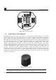
RXT-320 Wireless Modbus™ 1.0 1.1 Introduction Description The RXT-320 wireless transceiver is designed to take Modbus™ communication between devices to a wireless platform. The transceiver connects directly to a Modbus™ device and transfers Modbus™ data to/from the device through the transceiver’s wireless radio.
RXT-320 Wireless Modbus™ information back to the master unit’s transceiver, which then places that information on the bus for the master unit. Modbus Master Control Unit Remote Monitor Unit Model X40-N4X Muiti-Channel Gas Detection Control System Modbus Slave Devices detcon inc. d etcon inc. MODEL IR-700 P GM1 PGM 2 Z ERO SP A N H 2 S S ensor Figure 2 Typical Wireless Layout The transceiver provides for the following features/connectivity: 1.
RXT-320 Wireless Modbus™ NOTE: If there are multiple Modbus™ networks in the same vicinity each system must reside on a different RF Channel to keep data from one appearing on the other. The 802.15.4 standard also implements a mesh network allowing any RXT-320 transceiver to relay or repeat data between adjacent neighbors.
RXT-320 Wireless Modbus™ MA GND PWR B J6 SW1 24V B A J4 24V A AIN2 J7 J1 GND POWER IN (SOLAR) GND W/V W/BU W/GN W/BN J2 SW2 24V A GND WIRELESS PROGRAM J8 MODBUS OUT (WIRELESS) B W/BK AIN1 WIRELESS SENSOR MODBUS IN L9 SP2 SP1 SDA SCL PWR TERM PROGRAM GND J5 JP1 DISPLAY Figure 4 Model 100 Terminal Board 1.
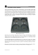
RXT-320 Wireless Modbus™ 1.5 Quad Battery Charger (Optional) Detcon’s Smart Battery Pack can be charged as needed using Detcon’s optional Quad Battery Charger which can charge up to four battery packs at one time. The Quad Battery Charger comes with a plug-in AC/DC adapter that plugs into a standard 120VAC outlet for power. The DC end of the adapter plugs into the DC power jack of the charger providing 24VDC.
RXT-320 Wireless Modbus™ 1.6 Solar Panel (Optional) Detcon also offers an optional solar panel to be used in conjunction with the Smart Battery Pack. It provides 24VDC output and connects to the J5 connector of the Model 100 Terminal Board. This option enables continuous operation of the wireless transceiver and charging of the battery pack eliminating the need for external recharging. It is an ideal choice for virtually any area with sufficient daily average sunlight.
RXT-320 Wireless Modbus™ 4. A good ground connection should be verified between the sensor’s metal enclosure and the junction box. If a good ground connection is not made, the sensor can be grounded to the junction box using the sensor’s external ground lug. Also verify a good ground connection between the junction box and earth ground. 5. Proper precautions should be taken during installation and maintenance to avoid the build-up of static charge on the plastic weather-guard of the transceiver. 6.
RXT-320 Wireless Modbus™ Wall (or other mounting surface ) 10" Typ. RXT Series Wireless Transceiver Detcon Mounting Plate (Optional ) 7 16" 3.5" mounting holes x4 15.7" 6.1" 3 4" NPT Ports 5.5" 7.135" 3 8" T-Outlet Box w/Drain mounting holes x4 5" 8" 1 4" 8-32 tapped ground point mounting holes x2 Custom Aluminum J-Box (For Battery Option ) 7" 2.5" Figure 9 RXT-320 Wireless Transceiver w/Battery Assembly and Mounting Dimensions 2.2.
RXT-320 Wireless Modbus™ Remote RXT-320 Wireless Transceiver Remote J-Box w/ 8-Position Terminal Board Remote 34" NPT T-Outlet Box w/Drain Power, Modbus & I²C Extension Cable to/from Remote RXT Transceiver Up to 15' Length 3 4" NPT Cord Connectors (Cable Glands) Required J-Box w/ Model 100 Terminal Board WIRELESS J1 External DC P ower In 7-30VDC mA - + TP1 NPT T-Outlet Box w/Drain RXT-320 Transceiver W/ W/ BU BK B R W BK R J6 J5 1 WB WA SB Spare ModBus J7 2 3 Smart Battery Pack J3 BK W
RXT-320 Wireless Modbus™ RXT-320 TRANCEIVER WIRING RED (POWER) BLACK (GND) RED (POWER) BLACK (GND) BLUE (MODBUS A) WHITE (MODBUS B) BLUE (MODBUS A) WHITE (MODBUS B) WHITE (MODBUS B) BLUE (MODBUS A) BLACK-GND RED (POWER) 700-Series Transient Protection PCA MA GND PWR B AIN2 J6 SW1 24V B A 24V J4 GND A J7 J1 MODEL 100 TERMINAL BOARD POWER IN (SOLAR) GND W/BU W/V W/BN W/GN J2 SW2 24V A B WIRELESS PROGRAM J8 MODBUS OUT (WIRELESS) GND W/BK AIN1 WIRELESS SENSOR MODBUS IN
RXT-320 Wireless Modbus™ Remote Mounting Steps 1. Remove the J-Box cover of the RXT-320 wireless transceiver assembly. 2. If the wireless transceiver assembly has the Smart Battery Pack, unplug the battery pack from the terminal board by pulling the battery pack out of the junction box. 3. Identify the J1 6-pin phoenix connector and the J8 3-pin phoenix connector on the Model 100 Terminal Board and disconnect from the board. Remove all transceiver wire connections from the connectors.
RXT-320 Wireless Modbus™ NOTE: Programming of RXT transceiver from the Model 100 Terminal Board will be disabled. 15. Plug battery pack back in place and reinstall the J-Box cover from step 1. Table 1 Extension Cable Wire Identification Function VDC Power (+) VDC Return (-) Modbus A (+) Modbus B (-) Serial Clock (SCL) Serial Data Line (SDA) Common Ground Common Ground Drain Wire 2.
RXT-320 Wireless Modbus™ If an external power source is installed, the RXT-320 wireless transceiver requires two conductor connections for the power supply. External DC power can be customer provided with an output voltage range between 7 to 30VDC or by Detcon’s optional 24VDC solar charging panel. Both of these alternatives will provide continuous operation of the assembly and can be installed in conjunction with the optional battery pack, providing a constant power source.
RXT-320 Wireless Modbus™ provide a complete solution to connecting an RXT-320 to power and providing high-current relay closures. When using interposing relays, it is strongly recommended to install a transient protection diode (1N4001) across the relay coil to mitigate the voltage spike when the coil is de-energized. RXT-320 Interposing Relay Alarm Output 1N4001 Diode From RXT-320 Processor Output Relay Coil MOSFET N-CH 50V 300mA V+ 49.
RXT-320 Wireless Modbus™ NOTE: The 4-20mA inputs do NOT support 4-wire implementations 2.3.5 Serial Clock & Serial Data Line This is the I2C interface for the transceiver consisting of a serial clock (SCL) and serial data line (SDA). These are used to monitor the status of the battery pack (if installed) and to read the value of the Modbus™ address switches of the Model 100 Terminal Board (if installed). 2.3.
RXT-320 Wireless Modbus™ NOTE: If using a Smart Battery Pack, battery pack removal is required to access the rotary switches for Modbus™ addressing and to access the board jumpers. Assigning a Modbus™ address to the transceiver allows registers within the transceiver itself to be accessed by the master and provide additional control and status from that transceiver.
RXT-320 Wireless Modbus™ NOTE: Transparent mode does not support accessing the internal registers of the transceiver through Modbus™ since there is no address assigned. Consequently many features are not available such as sleep, battery status, 4-20mA inputs and alarm outputs. 3.2 Master Configuration with Controller The RXT-320 wireless transceiver can function as a master when connected to a controller by assigning it a Modbus™ address of F0h through the transceiver’s Model 100 Terminal Board.
RXT-320 Wireless Modbus™ rather to drive relay coils which in turn will drive a higher current output. There are four RXT alarm output registers that become available when in alarm station mode. The four alarm outputs are controlled by four internal registers within the RXT-320 and can be controlled on all RXT-320 transceivers by writing to these four registers using the Modbus™ address assigned that transceiver.
RXT-320 Wireless Modbus™ 4.1 General Modbus™ Description The RXT-320 performs Modbus™ communication using the RTU transmission mode per the Modbus™ specification. The basic frame format for Modbus™ consists of a Modbus™ address, function code, data and CRC. Address Field Function Code Data CRC Figure 15 Modbus™ Frame Format As stated earlier, the Address Field is the unique Modbus™ address of each device for the whole system. The Function Code is the function to be performed.
RXT-320 Wireless Modbus™ 4.1.2 Modbus™ Broadcast Requests The Modbus™ broadcast request was introduced in the RXT-320 to support commands to be executed across all RXT-320 transceivers simultaneously. More specifically this is used to place all RXT-320s in a low power sleep state to conserve battery life. If none of the RXT-320s are battery powered there is no need to issue a sleep command.
RXT-320 Wireless Modbus™ Table 7 RXT-320 Register Map Register Access 8192 R 8193 R/W 8194 R/W 8195 R/W 8196 R/W 8197 R 8198 R 8199 R 8200 R 8201 R 8202 R/W 8203 R/W 8204 R 8205 R 8206 R/W 8207 R/W 8208 8209 8210 8211 – 8270 R R R Name Detcon Type Alarm 0 Output Alarm 1 Output Alarm 2 Output Alarm 3 Output 4-20mA A 4-20mA B Battery Life Percent Battery Life Minutes uC Version Sleep Time Control Status Battery Voltage I2C Batt Read Fails I2C Switch Read Fails Timestamp Secs High Timestamp Secs Low Time
RXT-320 Wireless Modbus™ 4.2.3 Register – 4-20mA Reading There are two 4-20mA inputs and their current value is stored in the 4-20mA A and B registers. The value of these register will range between 0 to 2048 with 0 being 0mA and 2048 being 20.48mA. Therefore a 4mA input will read 400 and a 20mA input will read 2000. Any currents above 20.48mA will remain at 2048 since this is the maximum value for this register. 4.2.
RXT-320 Wireless Modbus™ Upon power up, this register is set to 0 and the RXT-320 is not in low power mode. To place a network to sleep the controller will generate a broadcast request (Modbus™ address = 0) and do a single write (function code 06) to register 8202 with the number of seconds the network should go to sleep. During sleep there can be no access to any device on the network so the user will have to trade off sleep time versus getting device updates.
RXT-320 Wireless Modbus™ 4.2.10 Register – Timestamp Three registers are utilized to maintain a timestamp that increments on the microcontroller after power up. These are all set to 0 upon power up or a microcontroller reset. The first two registers 8208 and 8209 are internally combined into a single 32 bit register and incremented each second. The last register 8210 maintains the millisecond count and will count from 0 to 999 and start over again. 5.
RXT-320 Wireless Modbus™ 7.0 Specifications Frequency ISM 2.4GHz Range Indoor/ No Line of Sight: 1,000ft Outdoor RF Line of Sight (with external antenna): 3 Miles.
RXT-320 Wireless Modbus™ 7.
RXT-320 Wireless Modbus™ 7.2 Revision Log Revision 1.0 1.1 2.0 Date 05/19/10 11/12/10 04/12/11 2.1 08/02/12 RXT-320 Wireless IM Changes made Original Release. Update to table 1 Wire Identification Extensive revision and detail added to all aspects of manual. Updated board and wiring diagrams, updated spare part list Rev. 2.