
Instruction Manual


RXT-320 Wireless Modbus™
RXT-320 Wireless IM iv
Table of Figures
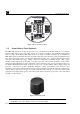
Figure 1 RXT-320 Wireless Transceiver Assembly...................................................................................... 1
Figure 2 Typical Wireless Layout................................................................................................................ 2
Figure 3 Mesh Network Topology.............................................................................................................. 3
Figure 4 Model 100 Terminal Board............................................................................................................ 4
Figure 5 Smart Battery Pack........................................................................................................................ 4
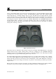
Figure 6 Quad Battery Charger.................................................................................................................... 5
Figure 7 Solar Panel .................................................................................................................................... 6
Figure 8 RXT-320 Approval Label............................................................................................................. 6
Figure 9 RXT-320 Wireless Transceiver w/Battery Assembly and Mounting Dimensions........................... 8
Figure 10 RXT-320 Wireless Transceiver Remote Mounting...................................................................... 9
Figure 11 Wiring Diagram for Remote RXT-320 Transceiver Mounting...................................................... 10
Figure 12 Internal Alarm Output Circuit ..................................................................................................... 14
Figure 13 Up to two Sensors using two 4-20mA Interfaces......................................................................... 14
Figure 14 Model 100 Terminal Board Rotary Switches................................................................................ 15
Figure 16 Modbus™ Frame Format............................................................................................................. 19
List of Tables
Table 1 Extension Cable Wire Identification................................................................................................ 12
Table 2 RXT-320 Transceiver Wire Identification ....................................................................................... 12
Table 3 Wire Gauge vs. Distance................................................................................................................. 13
Table 4 Model 100 Terminal Board Jumper Settings.................................................................................... 15
Table 5 RXT-320 Addressing and Operational Modes ................................................................................. 16
Table 6 Exception Codes............................................................................................................................. 19
Table 7 RXT-320 Register Map................................................................................................................... 21
Table 8 RXT-320 Secondary Alarm Output Register Map ........................................................................... 21