RXT Wireless Configuration Tool Operator’s Instruction Manual DETCON, Inc. 3200 Research Forest Dr., The Woodlands, Texas 77387 Ph.281.367.4100 / Fax 281.298.2868 www.detcon.com September 2, 2011 • Document # 3751 • Revision 0.
RXT Wireless Configuration Tool Page intentionally blank Shipping Address: 3200 A-1 Research Forest Dr., The Woodlands Texas 77381 Mailing Address: P.O. Box 8067, The Woodlands Texas 77387-8067 Phone: 888.367.4286, 281.367.4100 • Fax: 281.292.2860 • www.detcon.com • sales@detcon.
RXT Wireless Configuration Tool Table of Contents 1.0 1.1 2.0 2.1 2.2 3.0 Introduction.............................................................................................................................................. 1 Description ........................................................................................................................................... 1 Power and I/O Connections ...................................................................................................
RXT Wireless Configuration Tool Figure 10 Device(s) Tab.................................................................................................................................... 8 Figure 11 View/Edit Configuration File Screen................................................................................................ 10 Figure 12 RXT-300 Wireless Network Screen ................................................................................................. 11 Figure 13 My Network Section ....
RXT Wireless Configuration Tool 1.0 Introduction 1.1 Description The RXT Wireless Configuration Tool is a custom device designed to configure Detcon’s RXT-300 and RXT320 SmartWireless™ transceivers. These RXT series transceivers enable wireless communication between the controllers, sensors and alarm stations of any gas detection system.
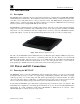
RXT Wireless Configuration Tool 2.2 USB SNAP Stick The SNAP Stick is a compact USB device used to enable the RXT WCT to communicate with RXT series transceivers. This device is about the size of a thumb drive and is designed to act as a bridge between an RXT wireless network and the WCT via its built-in wireless radio. The SNAP Stick connects to the WCT’s USB port located on its left side. Figure 2 USB SNAP Stick NOTE: The SNAP Stick is only needed for the WCT’s Wireless Network section.
RXT Wireless Configuration Tool • • • • • Identify RXTs to be set up on a single network using their serial numbers. Identify a new wireless network to place all RXTs. If there are unwanted RXTs on the new wireless network, identify a different unused network. Move unwanted RXTs to the different network. Move selected RXTs to new network. Upon completion, only the selected RXTs will be in the new wireless network.
RXT Wireless Configuration Tool 3.2 Main Configuration Tool Screen The main configuration tool screen offers six menu selections for the RXT-300 configuration tool and four menu selections for the RXT-320 configuration tool as well as a Shutdown button for both. These menu selections will in turn bring up separate screens when selected.
RXT Wireless Configuration Tool 3.3 Create Configuration File (RXT-300 Only) The Create Configuration File screen is available only for the RXT-300 configuration tool and can be selected from its main configuration tool screen. It is used for building a system configuration accordingly. This configuration can then be saved and loaded wirelessly to all RXT-300s specified in the configuration file.
RXT Wireless Configuration Tool System Name Network ID RF Channel Alphanumeric name for the Wireless Network – This field can be set to any desired value. Sets all RXT-300 radios in system to Network ID. (Values: 0-65534) Networks with different network IDs can occupy the same RF channel. Sets all RXT-300 radios in system to an RF channel. (Values: 0-15) NOTE: RXT-300s will only communicate with other RXT-300s with the same network ID and RF channel.
RXT Wireless Configuration Tool Figure 9 RXT(s) Tab RXT Name Alphanumeric name for the corresponding RXT-300 in the system which can be set to a meaningful name by the user. A maximum of 32 characters is allowed of which only the first 15 characters will appear on an HMI Panel display. Unique Device ID Uniquely identifies the RXT-300 using the serial number that is stamped on the metal back plate of the RXT-300 itself.
RXT Wireless Configuration Tool Alarm Out Events This is a submenu that allows the user to select which RXT-300 events will generate alarms and which relays will be triggered from the events. There are four events that are monitored: Network Down, RXT Offline, Battery Fault and Battery Alarm. All four RXT events default to relay 4 but can be individually assigned to any relay. Network Down occurs when no Master has been detected for an extended period.
RXT Wireless Configuration Tool Device Name Alphanumeric name for the corresponding sensor in the system which can be set to a meaningful name by the user. A maximum of 32 characters is allowed of which only the first 15 characters will appear on an HMI Panel display. Device Type The user can select from a pre-defined list of Detcon devices which will automatically populate some of the parameters for the user. The available device types are 100 Series, 600 Series, 600D Series, 700 Series and RXT-300.
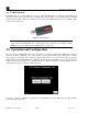
RXT Wireless Configuration Tool 3.4 View/Edit Configuration File (RXT-300 Only) The View/Edit Configuration File screen is available only for the RXT-300 configuration tool and can be selected from its main configuration tool screen. It is used for viewing and editing a configuration file that has been previously saved. To open a file, the user must first select the appropriate file from the available list and then select “Open”. Only one file may be selected at a time.
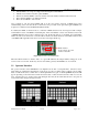
RXT Wireless Configuration Tool NOTE: RXTs that are part of an operational system are in constant communication with the master RXT. When searching for RXTs on an operational network, the WCT will temporarily disable sleep for the current network it is searching. The network sleep function is restored once the WCT has completed searching the network. Figure 12 shows the Wireless Network screen for the RXT-300 configuration tool after initialization has been completed.
RXT Wireless Configuration Tool NOTE: It is recommended that the Network ID be set to the same value as the Channel to simplify settings. 3.5.2 Operations The Operations section encompasses three main operations performed for both the RXT-300 and RXT-320. Search My Network Searches for RXTs in My Network. Results are listed in RXTs in My Network. Reboot RXT(s) Reboots the radios on RXTs that are selected in RXTs in My Network. Upload Image Changes the RXT’s image on RXTs selected in RXTs in My Network.
RXT Wireless Configuration Tool The Config Mode operation allows the user to turn ON or OFF the selected RXT’s configuration mode. This mode must be turned ON in order for the RXT to be configured. The Configure RXT(s) operation will configure the selected RXTs by loading it with the selected configuration file. The Restore NV Defaults operation will restore non-volatile memory with default parameters.
RXT Wireless Configuration Tool Select All Unselect All Clear Up/Down Arrows Selects all RXTs in the RXTs in My Network section including those not displayed if multiple pages are available. Unselects all RXTs in the RXTs in My Network section including those not displayed if multiple pages are available. Removes any RXTs that are selected in the RXTs in My Network section. These are page up and page down functions if multiple pages are available.
RXT Wireless Configuration Tool 3.5.4.2 Operations The Operations section has two operations available as defined below: Search Searches for RXTs determined by Search Channels. Results are listed in RXTs Found. Move to My Network Moves RXTs that have been selected in RXTs Found list to My Network.
RXT Wireless Configuration Tool NOTE: When searching for RXTs on an operational network, the WCT will temporarily disable sleep for the current network it is searching. The network sleep function is restored once the WCT has completed searching the network. The Search and Move to My Network are used for multiple purposes. The first is to determine what wireless networks have RXTs on them.
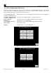
RXT Wireless Configuration Tool 3.5.6 Monitor Network The Monitor Network function provides the user a scrollable window to see network communication as timestamped logged events. Figure 23 Monitor Network Window 3.5.7 Network Activity The Network Activity section gives a visual representation of the activity of the current network selected. Two virtual LEDs are used to represent activity and sleep on the network.
RXT Wireless Configuration Tool Figure 25 File Manager Screen If the user desires to copy, move or delete files to a USB DRIVE, the USB DRIVE must be installed in the RXT WCT’s USB port. The RXT WCT will show the status of the USB DRIVE in red at the top left part of the screen. To use the USB DRIVE the RXT WCT must show USB Drive Mounted.
RXT Wireless Configuration Tool Figure 26 System Date and Time Screen 4.0 Example RXT-320 Configuration The RXT-320 configuration tool is simple to use and gives the user the ability to add/remove RXT-320s to/from specific wireless networks based on their Channel and Network ID. The first step is to identify the serial numbers of the RXT-320s that are of interest and what wireless network (Channel/Network ID) they need to reside in.
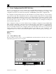
RXT Wireless Configuration Tool will list the results, if any, in the RXTs in My Network section. For example, in the figure below, the RXT WTC initialized to the current RF channel 3 and network ID 3. Eight RXT320s were found in this wireless network and listed in the RXTs in MY Network section. Figure 27 RXT-320 Wireless Network Screen NOTE: The search can be canceled at anytime by selecting the Cancel button if the RXTs being found are not relevant to the user. 5.
RXT Wireless Configuration Tool NOTE: The RXTs found from the previous search will remain on the list until they are manually removed. To remove them, choose Select All and then Clear. 6. Select the Search Other Networks button to find the five RXTs from the sample exercise. When entering this screen for the first time, the default channel will be the current channel set from the previous screen. 7.
RXT Wireless Configuration Tool 5.0 Example RXT-300 Configuration The RXT-300 configuration tool gives the user the ability to add/remove RXT-300s to/from specific wireless networks based on their Channel and Network ID plus allows the user the ability to configure RXT-300 wireless systems.
RXT Wireless Configuration Tool g. Enter “Zone 1 Example” as the zone name for Zone 1. h. Select the Save Zone button to save and create this zone. When saved, the zone section will increment to the next zone. Zones will not be created until the Save Zone button is selected. i. Enter “Zone 2 Example” as the zone name for Zone 2. j. Select the Save Zone button to save and create this zone. Figure 30 RXT-300 Create Configuration File Screen RXT Tab 6.
RXT Wireless Configuration Tool Figure 31 RXT 1 700 Sensor Add RXT for Sensor 2 9. Select the RXT Name field and enter “RXT 2_100 Sensor” for the second RXT. a. Enter 00.85.3A as its Unique Device ID. b. Select the Slave Device button since it will function as a slave device with a sensor attached. This button will turn red to indicate it has been selected. c. Select the Battery Attached button in the Alarm Stations/Battery section since it will be powered by a Detcon battery pack.
RXT Wireless Configuration Tool Add RXT for Alarm Station 10. Select the RXT Name field and enter “RXT 3 Alarm Station” for the third RXT. a. Enter 00.85.43 as its Unique Device ID. b. Select the Slave Device button since it will function as a slave device with an alarm station attached. This button will turn red to indicate it has been selected. c. Select the Alarm Station button in the Alarm Stations/Battery section since it will function as an alarm station.
RXT Wireless Configuration Tool Figure 34 RXT 4 Analog Sensor Add RXT for HMI 12. Select the RXT Name field and enter “RXT 5 HMI” for the fifth RXT. a. Enter 00.90.78 as its Unique Device ID. b. The HMI Attached button should already be selected as the default, if not, select it since it will function as a device with an HMI attached. This button will turn red to indicate it has been selected. c.
RXT Wireless Configuration Tool Device Tab 13. Select the third tab labeled Device(s) which is used to enter the configuration parameters pertaining to the RXT-300s that will be part of the wireless system. 14. Select the Add Device(s) button which turns on Add Mode and displays the first device with a default name of “Device 1”. This name can be changed by the user if desired and must be no more than 32 characters long. In our example, three devices will be added and configured. Add Model 700 Sensor 15.
RXT Wireless Configuration Tool c. Select the RXT field and select “RXT 2_100 Sensor” from the list. d. Select Done to save selection and exit the RXT screen. e. Because this device is a 100 series sensor with a fixed Modbus™ address of 1, change the Device Modbus Address from its default value of “2” to a value of “1”. f. Configure the alarm events accordingly per section 3.3.3 if needed. In our example, the default settings will not be changed. g.
RXT Wireless Configuration Tool i. Once the configuration of Device 3 is complete, select the Save Device button to save the configuration settings for the device. The Device section will increment to the next device to be configured by the user. Figure 38 Device 3 Analog Sensor Save Configuration 18. Once the configurations for all three tabs (Network/Zone(s), RXT(s), Device(s)) are complete, select the File Name field to enter a unique file name for the configuration.
RXT Wireless Configuration Tool Figure 39 RXT-300 Wireless Network Screen NOTE: The search can be canceled at anytime by selecting the Cancel button if the RXTs being found are not relevant to the user. 23. Select the Search Other Networks button to find the five RXTs from the sample exercise. When entering this screen for the first time, the default channel will be the current channel set from the previous screen. 24.
RXT Wireless Configuration Tool NOTE: Found RXTs will not clear automatically from the list if a search of a different channel is performed. Newly found RXTs will simply be added to the existing RXTs in the list. 26. Select the RXTs to be moved from the list individually or use the buttons at the bottom to select multiple RXTs. From our sample exercise, all five RXTs will be selected. 27.
RXT Wireless Configuration Tool 7.0 Specifications System Specifications Processor/Cache: Inputs: I/O Ports: System Memory: System Storage: Warranty: Intel Atom Z670 processor (1.5 Ghz) Touch (Capacitive Multi-Touch) and Pen (Active Stylus) 1 USB 1 Video Out (micro-HDMI, Type D) 1 SD Card Power Jack Dock Connector 1GB or 2GB 800MHz DDR2 30GB Solid State Drive (SSD) SATA 2.0 at 3.0Gb/s One year Electrical Specifications Input Voltage: Power Consumption: 100-240VAC~1.
RXT Wireless Configuration Tool 7.2 Revision Log Revision 0.0 Date 09/02/11 RXT WCT Instruction Manual Changes made Initial Release. Rev 0.