Model RXT-300 SmartWireless™ Transceiver Operator’s Installation and Instruction Manual DETCON, Inc. 4055 Technology Forest, Suite 100 The Woodlands, Texas 77381 Ph.281.367.4100 / Fax 281.298.2868 www.detcon.com January 03, 2012 • Document # 3481 • Revision 2.
RXT-300 SmartWireless™ Page intentionally blank Shipping Address: 4055 Technology Forest, Suite 100, The Woodlands Texas 77381 Mailing Address: P.O. Box 8067, The Woodlands Texas 77387-8067 Phone: 888.367.4286, 281.367.4100 • Fax: 281.292.2860 • www.detcon.com • sales@detcon.
RXT-300 SmartWireless™ Table of Contents 1.0 1.1 1.2 1.3 1.4 1.5 1.6 2.0 Introduction.............................................................................................................................................. 1 Description ........................................................................................................................................... 1 RXT-300 Wireless Radio .......................................................................................................
RXT-300 SmartWireless™ 5.0 Modbus Operation................................................................................................................................. 27 5.1 Modbus Addressing – Special Cases.................................................................................................. 28 5.1.1 Address Translation.................................................................................................................... 28 5.1.2 Accessing RXT-300 4-20mA Sensors...........
RXT-300 SmartWireless™ List of Tables Table 1 Extension Cable Wire Identification .................................................................................................... 11 Table 2 RXT-300 Transceiver Wire Identification ........................................................................................... 12 Table 3 Wire Gauge vs. Distance ...................................................................................................................... 13 Table 4 Exception Codes.....
RXT-300 SmartWireless™ Page intentionally blank Shipping Address: 4055 Technology Forest, Suite 100, The Woodlands Texas 77381 Mailing Address: P.O. Box 8067, The Woodlands Texas 77387-8067 Phone: 888.367.4286, 281.367.4100 • Fax: 281.292.2860 • www.detcon.com • sales@detcon.
RXT-300 SmartWireless™ 1.0 Introduction 1.1 Description The RXT-300 SmartWireless™ Transceiver is the foundation for the Detcon family of wireless products. Each RXT-300 comes with an internal multi-channel controller function that allows for monitoring and generating alarms in an industrial detection system. Communication between RXT-300s occurs wirelessly using the internal IEEE 801.15.4 radio.
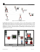
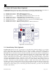
RXT-300 SmartWireless™ Figure 1 System Example utilizing the RXT-300 The RXT-300 is usually built up as part of an assembly to satisfy one of three different applications, the HMI (Human Machine Interface) Station for visual status of the network, the Sensor Station that has one or more sensors attached and the Alarm Station for system alarm indication. These three basic assemblies are then duplicated and located as needed by the customer.
RXT-300 SmartWireless™ The RXT-300 has been designed with multiple interfaces to support these three applications. There is a single RS-485 interface that utilizes the Modbus™ RTU protocol and can be set up as a Modbus™ Master or Modbus™ Slave. As a Modbus™ Master the interface will support up to four Modbus™ sensors and will poll the sensors and process alarms for those sensors.
RXT-300 SmartWireless™ 1.3 Model 100 Terminal Board (Optional) The RXT-300 wireless transceiver can be ordered with an optional Model 100 Terminal Board mounted in a condulet/J-Box (See Figure 4).
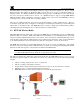
RXT-300 SmartWireless™ Figure 5 Smart Battery Pack NOTE: The RXT-300 wireless transceiver can also be powered by a customer provided external DC power source. Refer to section 0 for more details. 1.5 Quad Battery Charger (Optional) Detcon’s Smart Battery Pack can be charged as needed using Detcon’s optional Quad Battery Charger which can charge up to four battery packs at one time. The Quad Battery Charger comes with a plug-in AC/DC adapter that plugs into a standard 120VAC outlet for power.
RXT-300 SmartWireless™ When first powered on and with no battery packs connected to the charger, all the LED indicators on the Quad Charger should be green. When a battery pack is seated into a charging port, the “CHARGE” LED will change from green to red indicating the battery pack is not sufficiently charged. Once fully charged, the LED will change from red to green and the battery pack is ready to be used.
RXT-300 SmartWireless™ 2.0 Installation 2.1 Guidelines for Safe Use 1. Install unit only in areas with classifications matching with those described on the approval label. Follow all warnings listed on the label. Figure 8 RXT-300 Approval Label 2. Do not use in areas containing air saturation levels of Acetic Acid, Acetone, Ammonium Hydroxide, Fuel C, Diethyl Ether, Ethyl Acetate, Ethylene Dichloride, Furfural, N-Hexane, MEK, Methanol, 2Nitropropane, or Toluene. 3.
RXT-300 SmartWireless™ 2.2 Mounting The RXT-300 wireless transceiver should be vertically oriented and mounted to an explosion-proof enclosure or junction box. The J-Box contains the optional Model 100 Terminal Board. If a battery pack is used, Detcon’s custom J-Box is needed to accommodate both the terminal board and the battery pack plus a T-Outlet box with a drain is required (See Figure 9). The RXT-300 wireless transceiver assembly is typically mounted on a wall or pole.
RXT-300 SmartWireless™ 2.2.1 Remote Mounting The RXT-320 wireless transceiver is normally connected directly to the J-Box containing the battery/terminal board assembly. In situations where RF line-of-sight is diminished by obstructions, it may be necessary to remotely mount the wireless transceiver away from this J-Box. Remote separation distances of up to 15 feet are possible with the recommended cable.
RXT-300 SmartWireless™ NOTE: Programming of RXT transceiver from the Model 100 Terminal Board will be disabled.
RXT-300 SmartWireless™ diagram in Figure 11. Reference Table 2 RXT-300 Transceiver Wire Identification for color code identification. NOTE: Wires that are not used should be individually capped off and secured out of the way in the T-Outlet box so that they are not exposed to any active components, power, or ground. 7. Reconnect these 3 Phoenix connectors to their corresponding places back on the 8-position terminal board with Ground. 8.
RXT-300 SmartWireless™ 2.3 Wiring Connections / Functions Depending on use and function, the RXT-300 wireless transceiver can be wired in different ways to different devices. It is important to insure that the wiring is correct for the device to operate properly. Wire identification for the transceiver can be found in Table 2 RXT-300 Transceiver Wire Identification.
RXT-300 SmartWireless™ Table 3 Wire Gauge vs. Distance AWG Wire Dia. Meters Feet 22 20 18 16 14 0.723mm 0.812mm 1.024mm 1.291mm 1.628mm 700 1120 1750 2800 4480 2080 3350 5250 8400 13,440 Over-Current Protection 3A 5A 7A 10A 20A NOTE: Wiring table is based on stranded tinned copper wire and is designed to serve as a reference only. NOTE: The supply of power should be from an isolated source with over-current protection as stipulated in table. The output voltage range must be between 7-30VDC.
RXT-300 SmartWireless™ Interposing Relay RXT-300 Alarm Output 1N4001 Diode From RXT-300 Processor Output Relay Coil MOSFET N-CH 50V 300mA V+ 49.9K Figure 12 Internal Alarm Output Circuit Detcon alarm terminal boards are available that allow either AC or DC/Battery operation with the relays built onto the board. These boards provide a complete solution to connecting an RXT-300 to power and providing high-current relay closures.
RXT-300 SmartWireless™ reading will reach a maximum of 2048 for currents greater than 20mA. Electrically the 4-20mA interface supports 2-wire and 3-wire devices. Figure 14 Up to two Sensors using two 4-20mA Interfaces NOTE: The 4-20mA inputs do NOT support 4-wire implementations 2.3.5 Serial Clock & Serial Data Line This is the I2C interface for the transceiver consisting of a serial clock (SCL) and serial data line (SDA). These are used to monitor the status of the battery pack (if installed). 2.3.
RXT-300 SmartWireless™ each poll a different RXT-300 is queried and will transmit its data stored locally to the rest of the RXT-300s on the network. This continues until all RXT-300s are polled across the network. As part of the polling process the Master RXT-300 will also transmit its own data to the network at the appropriate time. The Master RXT-300 can be any one of the RXT-300s in the network but the “election” process can be guided by the user when the RXT-300s are configured and set up.
RXT-300 SmartWireless™ as well as process and store the alarm state of the sensor. The Sensor Station RXT-300 will transmit all its sensor data to the rest of the network when it is polled by the Master RXT-300. This data is then stored by every RXT-300 on the network and available for those RXT-300s to perform alarm processing or for user visibility through a HMI Station.
RXT-300 SmartWireless™ AV1-DV2 Strobe Horn Combo Alarm Station V2-DV2 Dual Strobe Alarm Station A1-DV2 Horn Only Alarm Station Figure 15 Basic C1D2 Wireless Alarm Stations Although not at Alarm station, the HMI Panel has four LEDs that provide a visible indication of the four alarm outputs. The HMI LEDs will follow the state of the alarm outputs and are labeled ALM 1, ALM 2, ALM 3 and FAULT.
RXT-300 SmartWireless™ 3.4.3 Alarm Setup Summary In summary, there are alarm events that are generated for multiple conditions around the system. For every alarm event they can be either ignored or they can be mapped into one of four Alarm Outputs. Alarm Zones provides additional mapping of these Alarm Outputs to specific groups of RXT-300s. Finally, the Alarm Outputs on each RXT-300 have properties to configure the way the Alarm Outputs operate.
RXT-300 SmartWireless™ Alarm Reset Only valid for Alarm Outputs with Latched property set. Will de-activate an Alarm Output that is Latched, but NOT if there is an existing Alarm. After alarm reset, a new Alarm event will cause latching of Alarm output again. Alarm Silence Only valid for Alarm Outputs with Silence-able property set. Will de-activate any Alarm Output, Latching or non-Latching. After alarm silence, a new Alarm event clears silence and will re-active Alarm Output.
RXT-300 SmartWireless™ NOTE: RF Silence can only be maintained while RXT-300 power is maintained. Any loss of power can cause a RXT-300 to reset and will cause some amount of wireless traffic to be generated as a result. It is up to the user to guarantee that power is maintained. As another option the user can remove power from any RXT-300 Stations where there may be a concern about power loss. NOTE: No sensor updates will occur during RF Silence.
RXT-300 SmartWireless™ Wireless Network The wireless network is the RF Channel and Network ID that the system will use to communication between RXT-300s. The main purpose here is to select a wireless network that is not in use by any other RXT-300s and that has minimum RF interference. If the user has no other RXT-300 systems in the area this meets the criteria of the first requirement.
RXT-300 SmartWireless™ 4.2.3 RXT-300 Build Info This section gives an overview of the data needed to configure a RXT-300. More may be needed as the complexity increases. RXT Name As each RXT-300 is added the user can choose a meaningful name to represent that RXT-300. The first several characters of this name will appear on an HMI Panel when displaying data about that RXT-300.
RXT-300 SmartWireless™ RXT This is the specific RXT-300 that the sensor is attached to and will be presented to the user in the WCT as a pull down list of RXT Names that were entered when adding RXT-300s earlier. Modbus™ Parameters This defines how the sensor will be accessed through Modbus™. All devices in a Modbus™ based system must have unique Modbus™ addresses which are addresses 1-247.
RXT-300 SmartWireless™ NOTE: RXT-300s will only communicate with other RXT-300s with the same network ID and RF channel. NOTE: Suggest using same Network ID as RF Channel which would allow for up to 16 systems (RF Channel / Network ID = 0-15). If configure two or more systems on same RF Channel but different Network IDs that are nearby they will have to share that channel, consequently it will take longer to poll and will cause data retransmits to occur. Network Sleep 4.3.
RXT-300 SmartWireless™ Associated Zones This is a submenu that allows the user to select which Alarm Zones this RXT-300 will be a part of. One or more Zones can be selected. There will only be one Zone if the default was taken in defining Zones. RXT Functions This is a submenu that defines the operation of Modbus on this RXT-300, if it is an Alarm Station and if it has a battery installed.
RXT-300 SmartWireless™ as Modbus™ address 4. So the HMI Panel will actually request sensor data from Modbus™ address 4 in this instance. Starting Address Defines the starting address used for poll the Modbus™ device Registers to Read Defines the number of Modbus™ registers to read. This is limited to 22 registers. Reading Register Defines the register that contains the concentration (reading) value used for Alarm processing and for displaying on the HMI Panel.
RXT-300 SmartWireless™ 5.1 Modbus Addressing – Special Cases 5.1.1 Address Translation The RXT-300 has the capability to take a unique Modbus™ system address and translating it to a different address on the local Modbus™ interface. In this way there can be local Modbus interfaces on multiple RXT-300s that have sensors with the same address but are addressed with unique system wide Modbus™ addresses. Each RXT-300 would be configured to perform the proper translation.
RXT-300 SmartWireless™ 5.2.1 Modbus™ Exceptions The RXT-300 is capable of returning Modbus™ exceptions when it cannot service a Modbus™ request meant for that RXT-300. By default this is turned off in the configuration since it can cause issues with some controllers that do not process Modbus™ exceptions.
RXT-300 SmartWireless™ Table 5 RXT-300 Register Map Register 0 1 2 3 4 5 6 7 8 9 10 – 15 16 17 – 18 19 20 – 44 45 46 47 48 49 50 51 – 66 67 51 – 71 72 73 – 98 99 100 101 102 – 4418 5.3.
RXT-300 SmartWireless™ 5.3.3 Register – 4-20mA Reading There are two 4-20mA inputs and their current value is stored in the 4-20mA A and B registers. The value of these register will range between 0 to 2048 with 0 being 0mA and 2048 being 20.48mA. Therefore a 4mA input will read 400 and a 20mA input will read 2000. Any currents above 20.48mA will remain at 2048 since this is the maximum value for this register. 5.3.
RXT-300 SmartWireless™ 5.3.7 Register – Radio Software Version This is set to a value based upon the version of software programmed into the RXT-300 radio. It is stored as two byte value representing the major and minor revision numbers. So a 0106h (262 decimal) represents a major version of 01 and minor version of 06. As software is updated this will be incremented appropriately. 5.3.8 Register – Control The Control register is must be written to carefully.
RXT-300 SmartWireless™ 6.0 Troubleshooting Guide Power Problems Probable Causes: Depleted battery/Low Charge, battery not seated properly. Recharge or replace battery. Reseat battery. Transceiver not Responding Probable Causes: Incorrect jumper settings on term board, incorrect wiring, connectors not seated properly. Verify jumper settings are properly configured. Verify transceiver wiring matches color coding on term board. Verify connectors are seated correctly and not offset.
RXT-300 SmartWireless™ 8.0 Specifications Frequency ISM 2.4GHz Range Indoor/No Line of Sight: 1,000ft Outdoor RF Line of Sight (with external antenna): 3 Miles. Spread Spectrum Digital-Sequence Spread Spectrum (DSSS) Modulation 0-QPSK Sensitivity -102dBm (1% PER) Inputs Two 4-20mA inputs Inputs/Outputs RS-485 Modbus™ RTU (9600bps) Power Input 7-30VDC Power Consumption Base RXT-300 unit: <500mW, 20 mA max at 24VDC Total Power is dependent on communication update rate between RXT-300 transceivers.
RXT-300 SmartWireless™ 8.
RXT-300 SmartWireless™ 8.2 Revision Log Revision 1.0 1.1 2.0 RXT-300 Wireless IM Date 05/19/10 11/12/10 01/03/12 Changes made Original Release. Update to table 1 Wire Identification Extensive revision and detail added to all aspects of manual. Rev. 2.
RXT-300 SmartWireless™ Programming Reset White/Violet Programming Data White/Green Programming Clock White/Blue RXT-300 Wireless Transceiver Power (+) Red Ground (-) Black Modbus B (-) White Modbus A (+) Blue SDA White/Brown SCL White/Black mA Green Solar Panel/ DC Power Power (+) Red Ground (-) Black Jumper Settings r e v i e c s n a r T 0 0 3 T X R 1 - SJ E RS IE WL 8 J e c 0a f 0r e 3 t n TI Xg Ro r P 6 J 3 J ︶ V / W /N WG /U WB A S - + d e s U t o N d e s U t o N t r y o n Pl gO o e r
RXT-300 SmartWireless™ RXT-300 Wireless Transceiver Programming Reset White/Violet Programming Data White/Green Programming Clock White/Blue SDA White/Brown Solar Panel/ DC Power SCL White/Black Power (+) Red Ground (-) Black Ground (-) Black Modbus A (+) Blue Power (+) Red Modbus B (-) White S S E L E R I W V / W ︶ ︵ 2 W S D A N G V 4 2 2 N I A ︶ A D N M G R W P 7 J 1 J 6 J 4 J Terminal Board N I R RA EL WO OS P 2 J 8 J T US OS E SL UE BR DI OW M ︵ B SM SA E LR EG RO I R WP U
RXT-300 SmartWireless™ mA Yellow mA Green Programming Reset White/Violet Programming Data RXT-300 Wireless Transceiver White/Green Programming Clock White/Blue Power (+) Red Ground (-) Black Modbus B (-) White Modbus A (+) Blue SDA White/Brown SCL White/Black Power (+) Red Ground (-) Black e c 0a f 0r e 3 t n TI Xg Ro r P 3 J k c a P y r e t t a B t r a m S t r y o n Pl gO o e rs P U 0 0n o 3 c -t T e XD R V / W /N WG /U WB 2 P T A S + - 1 2 3 4 5 6 7 d e s U t o N d e s U t o N ︵ 4 J 7 J
RXT-300 Wireless IM e c a 0f 0e r 3 t -n T XI g Ro r P 8 J 6 J r e v i e c s n a r T 0 0 3 T X R 1 - SJ E RS I E WL 5 J Rev. 2.0 V / W /N WG /U WB 2 P T R K B W U B /R WB /K WB 3 C C + Dn ID V lr a 0 ne w3 r e o5 t xP.
White/Green T US OS E SL UE BR DI OW M Rev. 2.