Model SW-HMI-32-N4X Model SW-HMI-32-N7 SmartWireless™ HMI Panel www.detcon.com Houston, Texas Operator’s Installation and Instruction Manual Covers all Model SW-HMI-32 Remote Displays DETCON, Inc. 4055 Technology Forest Blvd., Suite 100 The Woodlands, Texas 77381 Ph.281.367.4100 / Fax 281.298.2868 www.detcon.com March 27, 2012 • Document # 3650 • Revision 1.
HMI Panel Instruction Manual This page left intentionally blank Shipping Address: 4055 Technology Forest Blvd., Suite 100, The Woodlands Texas 77381 Mailing Address: P.O. Box 8067, The Woodlands Texas 77387-8067 Phone: 888.367.4286, 281.367.4100 • Fax: 281.292.2860 • www.detcon.com • sales@detcon.com SmartWireless HMI Panel Instruction Manual Rev. 1.
HMI Panel Instruction Manual Table of Contents 1.0 Introduction........................................................................................................................................1 1.1 1.2 1.3 1.4 1.5 1.6 1.7 2.0 Description ..................................................................................................................................................... 1 System Operation .............................................................................................
HMI Panel Instruction Manual Figure 9 AC/DC Inputs....................................................................................................................................7 Figure 10 SW HMI N4X Enclosure w/RXT-300 & Secondary SW HMI Panel.............................................8 Figure 11 RS-485 & Power Output Wiring for SW HMI N4X .......................................................................8 Figure 12 SW HMI Panel N7 Assembly Dimensions ..........................................
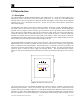
HMI Panel Instruction Manual 1.0 Introduction 1.1 Description The SmartWireless™ Human Machine Interface (SW HMI) panel is a read only remote display unit designed to operate with Detcon’s RXT-300 wireless transceivers. It consists of an SW HMI module which provides an operator interface to an RXT-300 network and displays real time status of all configured network devices up to a maximum of 32 devices. Devices can be sensors, alarm stations, repeaters and other remote displays.
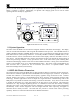
HMI Panel Instruction Manual power LCD with back light and ultra low power components that extend operating time for 1-2 months before a recharge is required. Additionally, an optional solar charging panel can be used to extend operating time for virtually any application. RXT-300 Transceiver Serial Number Plate SW HMI Mounting Plate SmartWireless HMI Panel Term Board & Smart Battery www.detcon.com Houston, Texas Figure 2 SW HMI Panel N7 Assembly 1.
HMI Panel Instruction Manual 1.4 Terminal Board and Smart Battery Pack (N7 Enclosure Only) The Model SW-HMI-32-N7 panel assembly comes with a custom terminal board (5143) and smart battery pack mounted inside an aluminum condulet.
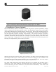
HMI Panel Instruction Manual Figure 4 Smart Battery Pack NOTE: The SW HMI panel can also be powered by a customer provided external DC power source on connector J5 of the terminal board with a voltage range of 11.5-30VDC. 1.5 Quad Battery Charger (Optional) Detcon’s Smart Battery Pack can be charged as needed using Detcon’s optional Quad Battery Charger which can charge up to four battery packs at one time.
HMI Panel Instruction Manual turns red without a battery pack connected to the charge port, then there is a problem or issue with the port and that port should no longer be used. Battery packs can remain connected to the charger even after a full charge indication (Green “Charge” LED) is shown due to the protection circuitry of the battery pack which prevents any overcharging issues. 1.
HMI Panel Instruction Manual 2.0 Installation (N4X Enclosure) 2.1 Mounting Securely mount the Model SW-HMI-32-N4X per the mounting dimensions provided in Figure 8. Provide for suitable conduit/cable entries in the bottom, top or sides of the enclosure and use required cable glands to maintain enclosure rating. Keep AC power separate from DC power and signals within conduit runs. 11.85" 6.8" 6.47" 8" Ø0.31" Mounting Bracket MODEL RD-64X-N4X Remote Display 13.73" 12.
HMI Panel Instruction Manual I O O O 24VDC 5A I NEU (L2) 2A I VAC (L1) GROUND 2A Figure 9 AC/DC Inputs 2.2.2 DC Power Input For optional external DC power input, connect 11.5-30VDC to the terminals of the DIN rail mounted terminal block labeled “24VDC” and “DC Comm” (See Figure 9). This input can be used for primary power or back-up power in the event of an AC power failure. The DC input voltage source should be capable of delivering at least 2.
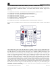
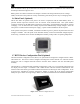
HMI Panel Instruction Manual RXT-300 Wireless Transceiver SW HMI Condulet w/ 8-Position Terminal Board 3 4" NPT T-Outlet Box w/Drain Master Port COMM1 Slave Port COMM2 3 4" 3 4" NPT Cord Connector (Cable Gland) Required SW HMI to RXT-300 Modbus & Power Cable NPT Cord Connectors (Cable Glands) Required SW HMI to Secondary SW HMI Modbus Cable Secondary SW HMI RS-485 Master Port Figure 10 SW HMI N4X Enclosure w/RXT-300 & Secondary SW HMI Panel RXT-300 Transceiver Black (Gnd -) White/Brown (Serial
HMI Panel Instruction Manual 3.0 Installation (N7 Enclosure) 3.1 Mounting The Model SW-HMI-32-N7 panel comes assembled with an RXT-300 transceiver and a Smart Battery Pack enclosed in an aluminum condulet with a custom terminal board. This assembly is attached to a custom mounting plate making installation simple and easy onto a rigid pipe or structure with the two 2 ½” U-bolts provided (refer to Figure 12). 25" RXT-300 Transceiver 22" Serial Number Plate SW HMI Mounting Plate SmartWireless HMI Panel 3.
HMI Panel Instruction Manual RXT-300 Wireless Transceiver SmartWireless HMI Panel Modbus, Power, I²C & Programming to RXT-300 R BK W BU W/BR W/BK J5 ed Us t No og e Pr ac rf XT te R In J6 J8 1 TP Modbus & Power to SW HMI N7 Panel r ve ei sc an Tr 00 -3 XT R J1 ER SS WI LE NPT T-Outlet Box w/Drain Condulet w/ Terminal Board ck Pa y er tt Ba rt ma S SA - + www.detcon.
HMI Panel Instruction Manual The wiring for the J7 connector is defined as follows, PWR/GND: A1/B1: A2/B2: SW: DC power connection from J2 of the terminal board. (11.5-30VDC) Primary ModbusTM connection (COMM1 Master) from J2 of the terminal board. Secondary ModbusTM connection (COMM2 Slave) to another remote display. *Contact Detcon for wiring instructions when using the A2/B2 pin outs* External switch connection for RESET/ACK function.
HMI Panel Instruction Manual 4.0 Initial Start-up The HMI display will power up as soon as power is applied. There is no external power switch to the unit. NOTE: Before applying power, check to make sure that all the wiring connections and external devices are installed correctly. NOTE: Applying power with devices hooked up incorrectly may cause damage to the equipment.
HMI Panel Instruction Manual 5.1.1 PROG Switch From the Main Display, the PROG switch enters into the Main Menu. Once inside the Main Menu, the PROG switch acts as an “Escape” switch that moves backwards in the menu flow chart. NOTE: While in Main Menu mode there are no updates to gas readings and hence no alarms will take place. 5.1.2 “u” Up Arrow Switch This switch moves the user up the Main Menu flow chart. It is also used to change selected entries within menu selections in the upward direction.
HMI Panel Instruction Manual displaying the next 4 sensors and so on. The HMI will then proceed to display all other devices on the network such as alarm stations, repeaters and other HMIs including itself up to 4 at one time, until the LCD cycles back to the first 4 sensors and repeats the process. When the HMI is in alarm, the display will stay on the group with the device in alarm. If two or more devices in different groups are in alarm, then the display will cycle through all the groups with alarms.
HMI Panel Instruction Manual Use the down arrow “v” switch to move to the next menu item or use the up arrow “u” switch to move to the previous menu item by swiping the programming magnet over the corresponding markers. Swiping the PROG switch again will return the unit to normal operation. When the appropriate Menu Item is found, the ENTER switch is used to enter that menu item by swiping the ENTER marker.
HMI Panel Instruction Manual 5.3.1 Auto Configure System The AUTO CONFIGURE SYSTEM menu is used to automatically configure the HMI panel when a properly configured wireless network is available. When this feature is activated, the HMI will search for RXT-300 wireless transceivers in the configured network by polling their Modbus™ addresses.
HMI Panel Instruction Manual RF SILENCE & ALARM INHIBIT RF SILENCE | INHIBIT:##:## TURN: ON | OFF | START #|# | Select the function by swiping the magnet over the markers of the up or down arrows to move the arrow prompt “→” to the desired location. A swipe over the “ENTER” marker will activate the selected function. RF SILENCE is used to prevent the radios from possibly interfering with other RF devices on site (such as remote detonators). Once set to ON, it will stay on until the user turns it OFF.
HMI Panel Instruction Manual This will end the system diagnostics test and the display will revert back to the SYSTEM DIAGNOSTICS menu. 5.3.6 Display Settings The DISPLAY SETTINGS menu allows the user to customize the brightness, contrast and backlight duration of the display.
HMI Panel Instruction Manual 7.0 Specifications Capacity 32 Input Devices Power Input N4X Input Voltage: N7 Input Voltage: 100-240VAC, 45-65Hz 11.5-30VDC 11.5-30VDC Power Consumption Nominal: Maximum: .07 Watt @ 11.5VDC 1.2 Watts @ 11.5VDC (Includes Display w/Backlight and 4 LED’s active) Display 1¼” x 6” Backlit LCD RFI/EMI Protection Complies with EN61326 Electrical Classification NEMA 4X or NEMA 7 Dimensions N4X Dimensions: N7 Dimensions: 11.85”W x 13.73”H x 6.47”D 25”W x 15.5”H x 7.
HMI Panel Instruction Manual 8.