
Manual

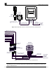
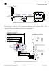


Table Of Contents
HMI Panel Instruction Manual
SmartWireless HMI Panel Instruction Manual Rev. 1.0 Page 7 of 20
O
I
2A
O
I
5A
O
I
2A
24VDC
GROUND
VAC (L1)
NEU (L2)
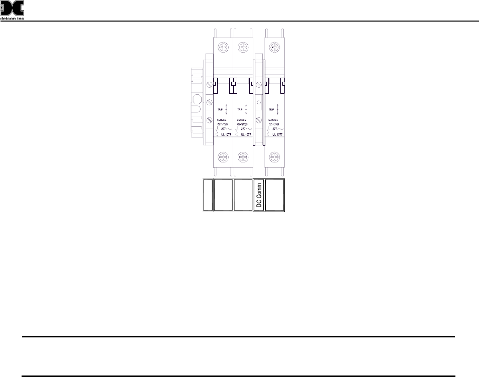
Figure 9 AC/DC Inputs
2.2.2 DC Power Input
For optional external DC power input, connect 11.5-30VDC to the terminals of the DIN rail mounted
terminal block labeled “24VDC” and “DC Comm” (See
Figure 9). This input can be used for primary
power or back-up power in the event of an AC power failure. The DC input voltage source should be
capable of delivering at least 2.5 Amps of current to the load (60 Watts @ 24VDC) which will power an
RXT-300 transceiver plus up to eight serial sensors.
NOTE: The supply of power should be from an isolated source with over-current protection.
The input voltage range must be between 11.5-30VDC. All wired Modbus™ devices
connected to the SW-HMI-32-N4X must have a common ground.
2.2.3 Modbus and DC Power Output
The serial RS-485 (Modbus™) and power to the RXT-300 (Slave) being monitored by the SW-HMI-32-
N4X remote display (COMM1 Master) is provided through the terminals of the DIN rail mounted terminal
block labeled “RS-485 MASTER” and “VDC Out” (See
Figure 11). The serial RS-485 connection labeled
“RS-485 SLAVE” is used to connect to another remote display where the SW-HMI-32-N4X will be seen as
a slave device in that specific Modbus™ loop. RS-485 connections require 24 AWG, two conductor,
shielded, twisted pair cable. Belden P/N 1502P is recommended for a single cable providing both serial
communications and power. Belden P/N 9841 is recommended for a single cable providing serial
communications only. For the N4X enclosure, the RXT-300 transceiver, terminal board (8-Position) and
condulet assembly are ordered separately.