
Manual
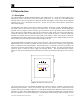
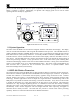
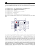
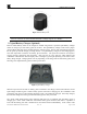
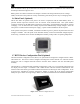
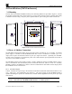
Table Of Contents

HMI Panel Instruction Manual
SmartWireless HMI Panel Instruction Manual Rev. 1.0 iii
Table of Contents
1.0 Introduction........................................................................................................................................1
1.1 Description ..................................................................................................................................................... 1
1.2 System Operation ........................................................................................................................................... 2
1.3 RXT-300 Wireless Transceiver...................................................................................................................... 2
1.4 Terminal Board and Smart Battery Pack (N7 Enclosure Only)...................................................................... 3
1.5 Quad Battery Charger (Optional) ................................................................................................................... 4
1.6 Solar Panel (Optional) .................................................................................................................................... 5
1.7 RXT Wireless Configuration Tool (Optional)................................................................................................ 5
2.0 Installation (N4X Enclosure) ............................................................................................................6
2.1 Mounting ........................................................................................................................................................ 6
2.2 Power & Modbus Connections....................................................................................................................... 6
2.2.1 AC Power Input .......................................................................................................................6
2.2.2 DC Power Input.......................................................................................................................7
2.2.3 Modbus and DC Power Output ...............................................................................................7
3.0 Installation (N7 Enclosure) ...............................................................................................................9
3.1 Mounting ........................................................................................................................................................ 9
3.2 Modbus & Power Connections....................................................................................................................... 9
3.3 Optional Remote Alarm Reset/Acknowledge Switch (N7 Enclosure) ......................................................... 11
4.0 Initial Start-up .................................................................................................................................12
5.0 System Operation and Configuration............................................................................................12
5.1 Operator Interface......................................................................................................................................... 12
5.1.1 PROG Switch.........................................................................................................................13
5.1.2 “
u
” Up Arrow Switch............................................................................................................13
5.1.3 “
v
” Down Arrow Switch .......................................................................................................13
5.1.4 ENTER and RESET/ACK Switch ...........................................................................................13
5.2 Main Display Functions ............................................................................................................................... 13
5.3 Menu Functions............................................................................................................................................ 14
5.3.1 Auto Configure System...........................................................................................................16
5.3.2 Response Timeout & Interpoll Delay.....................................................................................16
5.3.3 RF Silence & Inhibit Timers ..................................................................................................16
5.3.4 Alarm Test Mode....................................................................................................................17
5.3.5 System Diagnostics ................................................................................................................17
5.3.6 Display Settings .....................................................................................................................18
5.3.7 About System..........................................................................................................................18
6.0 Warranty ..........................................................................................................................................18
7.0 Specifications....................................................................................................................................19
8.0 Spare Parts .......................................................................................................................................20
9.0 Revision Log.....................................................................................................................................20
Table of Figures
Figure 1 SW HMI Panel N4X Enclosure.........................................................................................................1
Figure 2 SW HMI Panel N7 Assembly ...........................................................................................................2
Figure 3 Terminal Board .................................................................................................................................3
Figure 4 Smart Battery Pack............................................................................................................................4
Figure 5 Quad Battery Charger........................................................................................................................4
Figure 6 Solar Panel.........................................................................................................................................5
Figure 7 RXT Wireless Configuration Tool ....................................................................................................5
Figure 8 N4X Enclosure Dimensional Overview ............................................................................................6