DIGITAL PHYSICIAN Eye-Level Scale Model 6437 Series Operating Instructions 0033-M114-O1 Rev F 10/12 CARDINAL SCALE MFG. CO. PO BOX 151 x WEBB CITY, MO 64870 PH (417) 673-4631 x FAX (417) 673-5001 www.detectoscale.com Technical Support: Ph: 866-254-8261 x techsupport@cardet.
DIGITAL PHYSICIAN EYE-LEVEL SCALE Thank you for purchasing our Detecto Digital Physician Eye-Level Model 6437 Series Scale. It has been manufactured with quality and reliability at our factory in Webb City, MO USA. Your scale has been tested before leaving our factory to insure accuracy and dependability for years to come. This manual is provided to guide you through the operation of your scale. Please read it thoroughly before attempting to operate your scale and keep it handy for future reference.
UNPACKING INSTRUCTIONS x Remove scale from carton by lifting up with equal force from column and platform base. x Check for any damage incurred in shipping. If scale has been damaged, place a claim with the carrier. Use the original carton and shipping material to return the scale. x Remove all plastic wrapping, foam fillers and cardboard material from the scale.
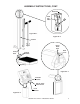
ASSEMBLY INSTRUCTIONS, CONT. Grommet Load Cell Cable C Figure No. 1 Figure No. 3 Column Raise Draft Rod Draft Rod Push Lever Column Bracket Opening Figure No. 4 Indicator Bracket #10-32 Truss Head Screw Lock Washer Figure No.
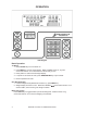
OPERATION 758C Keypad Basic Operation To Weigh 1. Press ON/OFF key to turn indicator on. 2. Press ZERO key to zero weight display. ZERO, GROSS and lb, oz, kg or ST annunciator will turn on to show that the scale is ready for use. 3. Place patient on scale and read weight display. 4. If a printer is connected to scale, press PRINT/ENTER key to print a ticket. 5. Remove patient from scale. Zero Weight Display 1. In Gross Weight mode (GROSS annunciator on), press ZERO key. 2.
OPERATION, CONT. Basic Operation with ID – (No BMI) To Weigh 1. Press ON/OFF key to turn indicator on. 2. Press ZERO key to zero weight display. ZERO, GROSS and lb, oz, kg or ST annunciator will turn on to show scale is ready for use. 3. Press ID/HEIGHT key. 4. Display will change to show id=. 5. Using numeric keys, key-in up to an 11 digit identification number. 6. Press PRINT/ENTER key. 7. Place patient on scale 8. Read weight display. 9.
OPERATION, CONT. Body Mass Index (BMI) Operation with ID To Weigh and Calculate BMI 1. Press ON/OFF key to turn indicator on. 2. Press ZERO key to zero weight display. ZERO, GROSS and lb, oz, kg or ST annunciator will turn on to show scale is ready for use. 3. Press ID/HEIGHT key. 4. Display will change to show id=. 5. Using numeric keys, key-in up to an 11 digit identification number. 6. Press PRINT/ENTER key. 7. Place patient on scale. 8. Press ID/HEIGHT key. 9.
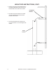
HEIGHT ROD INSTRUCTIONS Height Rod Hole Location 2in (51mm) Please check the Height Rod hole locations before installing the Height Rod. x Some scales may require holes to be drilled. x Please follow the measurements for drilling holes if necessary. x After holes have been drilled, please follow installation instructions. 9/64” 47/64” 29 (75.5 cm) IMPORTANT! (3.5mm) diameter holes, 1” (25.4mm) from center of column to center of hole Measure from bottom of column, not floor or scale base.
HEIGHT ROD INSTRUCTIONS, CONT. 3. Place the large end of the slotted holes in the height rod brackets over the four hex head screws on the back of the column. Height Rod Bracket 4. Pull down to set the screws in the small end of the slotted hole and secure the bracket to the column. 5. Use the included wrench to tighten the hex head screws. Do not over-tighten the screws.
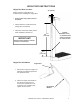
HEIGHT ROD INSTRUCTIONS, CONT. Height Rod Operating Guide 1. Before patient steps onto scale platform, spoon (B) should be rotated to horizontal position, and raised well above patient's apparent height. 2. Patient may now step onto scale platform. Spoon (B) should be held horizontal and above patient's head. A B C E 3. Carefully lower spoon (B), keeping it horizontal, until it rests gently on top of patient's head. If patient is shorter than 3' 4" (101.
DIGITAL HEIGHT ROD INSTRUCTIONS Digital Height Rod Installation Before starting installation, please unpack carefully and remove all plastic wrappings, foam fillers and cardboard material. You should have the following components: (1) Detecto Digital Height Rod (DHR) (2) Mounting Brackets (1) Hardware Pack, containing: (8) M4x0.7x4 Pan Head Machine Screws (bracket to height rod) (4) #10x1/2” Hex Head Sheet Metal Screws (bracket to column) 1.
DIGITAL HEIGHT ROD INSTRUCTIONS, CONT. Measuring Patient’s Height IMPORTANT! Before performing the operations on this page, the digital height rod must be in its “starting position” (inner sliding tube must be down completely inside outer stationary tube and headpiece folded flat against stationary tube) prior to turning on the indicator. Otherwise, the error message 999.9 will be displayed. 1. Make sure height rod is in starting position. 2. Press ON/OFF key to turn indicator on. 3.
ERROR AND STATUS DISPLAYS Display -Err-OF-trL-UnSCALib AdErr ErrA ErrAL ErrAH EE Err OCAP OFF Meaning General error, invalid keypad entry was attempted. Attempting to display a negative number greater than –9,999 or a positive number greater than 99,999 Indicates an attempt to zero a weight outside scale zero range. Refer to the Setup and Calibration trL= (Four Percent Zero Tracking Range Limit) parameter.
PARTS IDENTIFICATION ITEM 1 6 7 20 21 22 23 24 25 26 27 29 30 33 35 36 37 38 39 42 43 45 46* 48 QTY 1 1 1 1 4 1 4 10 10 4 1 1 1 1 1 2 1 1 1 1 1 2 1 2 2 1 1 1 PART NUMBER 758C 6800-1045 0033-B163-0A 0044-C180-1A 3P8059 2U58 3P2087 6021-1102 6024-1027 63K1038 3P2011X 3P511X 3P868 3P9068 0033-C106-1A 6021-1629 0033-D063-1A 0033-D475-1A 0033-B256-08 3P8002X 3P8003X 3P60 6021-1454 6021-1045 6024-0049 0033-B104-0A 709G2R1206 3P1001X DESCRIPTION DIG. WT. IND.
PARTS IDENTIFICATION, CONT.
FCC COMPLIANCE STATEMENT WARNING! This equipment generates uses and can radiate radio frequency and if not installed and used in accordance with the instruction manual, may cause interference to radio communications. It has been tested and found to comply with the limits for a Class A computing device pursuant to Subpart J of Part 15 of FCC rules, which are designed to provide reasonable protection against such interference when operated in a commercial environment.
STATEMENT OF LIMITED WARRANTY Detecto Scale warrants its equipment to be free from defects in material and workmanship as follows: Detecto warrants to the original purchaser only that it will repair or replace any part of equipment which is defective in material or workmanship for a period of one (1) year from date of shipment. Detecto shall be the sole judge of what constitutes a defect.
STATEMENT OF LIMITED WARRANTY Conditions Which Void Limited Warranty This warranty shall not apply to equipment which: A.) Has been tampered with, defaced, mishandled or have had repairs and modifications not authorized by Detecto. B.) Has had serial number altered, defaced, or removed. C.) Has not been grounded according to Detecto’s recommended procedure. Freight Carrier Damage Claims for equipment damaged in transit must be referred to the freight carrier in accordance with freight carrier regulations.
18 0033-M114-O1 Rev F x Model 6437 Series